
Arylamine compound and synthetic method thereof

a technology of arylamine compound and synthetic method, which is applied in the direction of discharge tube luminescnet screen, organic chemistry, natural mineral layered products, etc., can solve the problems of material gradually deterioration, difficult to obtain character, and degradation of light emitting elements, etc., to achieve excellent hole transporting property, excellent hole injecting property, and high reliability

Inactive Publication Date: 2007-02-15
SEMICON ENERGY LAB CO LTD
View PDF36 Cites 20 Cited by
  • Summary
  • Abstract
  • Description
  • Claims
  • Application Information

AI Technical Summary

Benefits of technology

[0024] A tertiary arylamine compound obtained by using the secondary arylamine compound of the present invention has an excellent hole transporting property and an excellent hole injecting property. In addition, the tertiary arylamine compound is easily oxidized and the tertiary arylamine compound in an oxidation state is stable, and returns to a neutral state by subsequent reduction. In other words, the tertiary arylamine compound obtained by using the secondary arylamine compound of the present invention is stable even when an oxidation state and a neutral state are repeated by an oxidation reaction and a reduction reaction subsequent to the oxidation.
[0025] A material for a light emitting element, which is the tertiary arylamine compound obtained by using the secondary amine compound of the present invention, is stable even when an oxidation state and a neutral state are repeated by an oxidation reaction and a reduction reaction subsequent to the oxidation. This means that the tertiary arylamine compound has resistance to repeated oxidation reactions. Therefore, by using the material for a light emitting element of the present invention, a light emitting element and an electronic device which have high reliability and long life can be obtained.

Problems solved by technology

This characteristic is difficult to be obtained by using a point light source typified by an incandescent lamp or an LED or by using a line light source typified by a fluorescent lamp.
There are many problems related to materials in improving characteristics of the light emitting element.
When a material which is easily decomposed by the oxidation reaction or the reduction reaction is contained in the layer containing a light emitting substance, the material gradually deteriorates by the repeated oxidation reactions or repeated reduction reactions, and the light emitting element itself deteriorates.

Method used


Image

  • Arylamine compound and synthetic method thereof
  • Arylamine compound and synthetic method thereof
  • Arylamine compound and synthetic method thereof

Examples


embodiment mode 1

[0051] A secondary arylamine compound and a synthetic method thereof according to the present invention will be described.

[0052] The secondary arylamine compound of the present invention is represented by General Formula 1.

(In the formula, Ar11 is an aryl group having 7 to 25 carbon atoms or a heteroaryl group having 7 to 25 carbon atoms. Ar12 and Ar13 may be identical or different, and are individually either an aryl group having 6 to 25 carbon atoms or a heteroaryl group having 5 to 9 carbon atoms. X is either a bivalent aromatic hydrocarbon group having 6 to 25 carbon atoms or a bivalent heterocyclic group having 5 to 10 carbon atoms.)

[0053] As the aryl group having 6 to 25 carbon atoms, specifically, a phenyl group, a 4-biphenylyl group, a 1-naphthyl group, a 2-naphthyl group, a 9-anthryl group, a 9-phenanthryl group, a 1-pyrenyl group, a 9,9′-dimethyl-2-fluorenyl group, a 9,9′-diphenyl-2-fluorenyl group, a spiro-9,9′-bifluorene-2-yl group, or the like can be used. Further,...

embodiment mode 2

[0066] Embodiment Mode 2 will describe a material for a light emitting element, which can be obtained by using a secondary arylamine compound of the present invention.

[0067] As one mode of the material for a light emitting element using the secondary arylamine compound shown in Embodiment Mode 1, a carbazole derivative represented by General Formula 4 can be used.

(In the formula, Ar11 is an aryl group having 7 to 25 carbon atoms or a heteroaryl group having 7 to 25 carbon atoms. Ar12 and Ar13 may be identical or different, and are individually either an aryl group having 6 to 25 carbon atoms or a heteroaryl group having 5 to 9 carbon atoms. X is either a bivalent aromatic hydrocarbon group having 6 to 25 carbon atoms or a bivalent heterocyclic group having 5 to 10 carbon atoms. R1 is any one of hydrogen, an alkyl group having 1 to 6 carbon atoms, an aryl group having 6 to 25 carbon atoms, a heteroaryl group having 5 to 9 carbon atoms, an arylalkyl group, or an acyl group having ...

embodiment mode 3

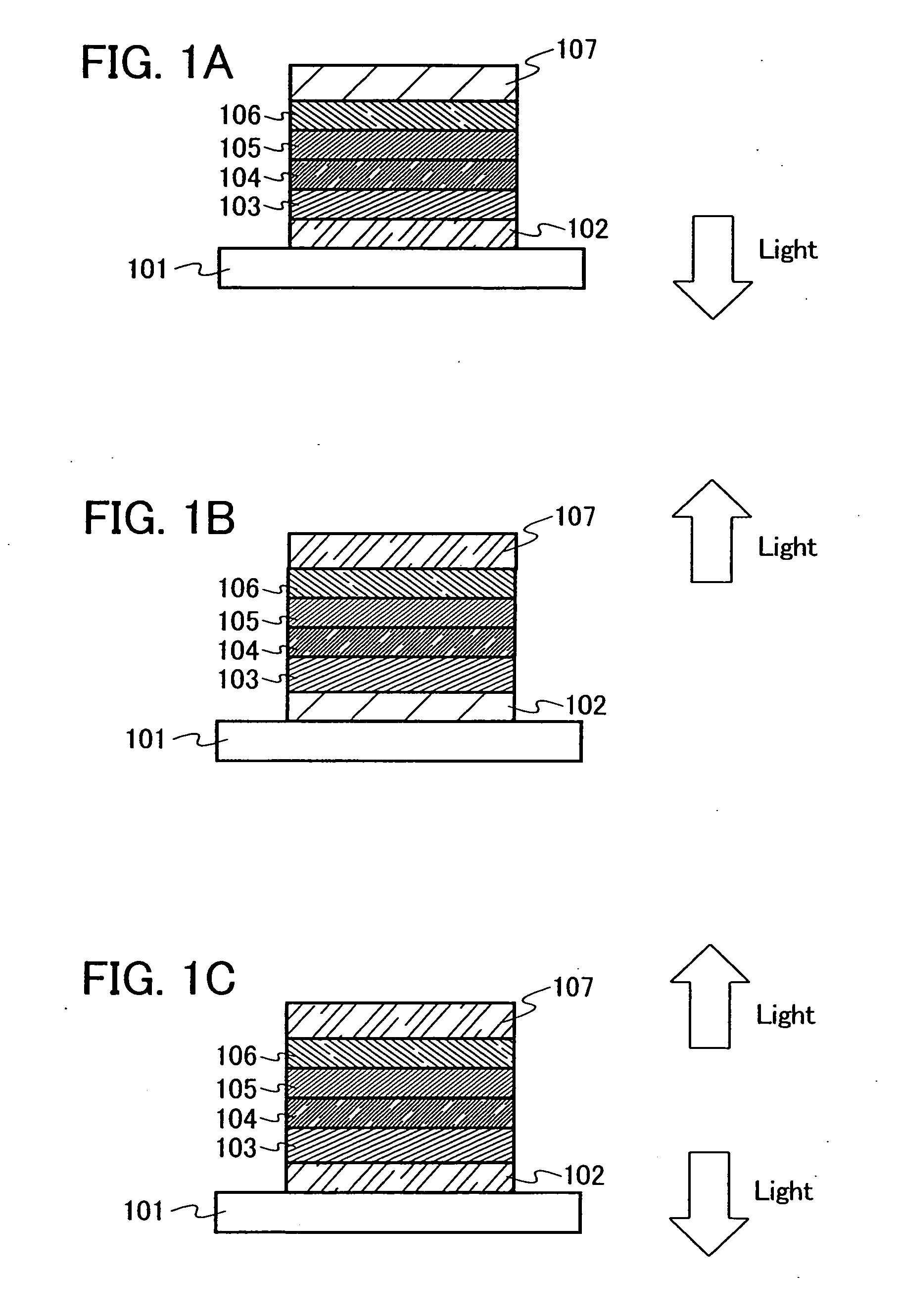
[0084] One mode of a light emitting element which uses the material for a light emitting element obtained by using a secondary arylamine compound of the present invention will be described with reference to FIG. 1A.

[0085] The light emitting element of the present invention includes a plurality of layers between a pair of electrodes. The plurality of layers are stacked layers formed by combining layers containing a substance having a high carrier injecting property or a high carrier transporting property, so that a light emitting region is formed in a place which is away from the electrodes, that is, so as to perform recombination of carriers in a portion which is away from the electrodes.

[0086] In this embodiment mode, the light emitting element includes a first electrode 102; a first layer 103, a second layer 104, a third layer 105, and a forth layer 106 which are sequentially stacked over the first electrode 102; and a second electrode 107 further provided thereover. The followi...


PUM

PropertyMeasurementUnit
Electrical resistanceaaaaaaaaaa
Lightaaaaaaaaaa

Abstract

It is an object of the present invention to provide an arylamine compound which has resistance to repeated oxidation reactions. The present invention provides a secondary arylamine compound represented by General Formula 1. (In the formula, Ar11 is an aryl group having 7 to 25 carbon atoms or a heteroaryl group having 7 to 25 carbon atoms. Ar12 and Ar13 may be identical or different, and are individually either an aryl group having 6 to 25 carbon atoms or a heteroaryl group having 5 to 9 carbon atoms. X is either a bivalent aromatic hydrocarbon group having 6 to 25 carbon atoms or a bivalent heterocyclic group having 5 to 10 carbon atoms.)

Description

TECHNICAL FIELD [0001] The present invention relates to an arylamine compound and a synthetic method thereof. In addition, the present invention relates to a material for a light emitting element obtained by using an arylamine compound, and a light emitting element and an electronic device manufactured by using the material for a light emitting element. BACKGROUND ART [0002] In recent years, research and development of a light emitting element using a light-emitting organic compound have been actively carried out. A basic structure of the light emitting element is such that a layer containing a light-emitting organic compound is sandwiched between a pair of electrodes. By applying a voltage to this element, electrons and holes are injected into the layer containing a light-emitting organic compound from the pair of electrodes so that a current flows. Then, the carriers (electrons and holes) are recombined, so that the light-emitting organic compound forms an excited state, and when ...

Claims


Application Information

Patent Timeline
IPC IPC(8): H01L51/54H05B33/14C07C211/00C07D209/88
CPCC07C211/58H01L51/5237C07C225/22C07C2103/18C07C2103/26C07C2103/97C07D209/88C07D213/74C07D239/74C07D277/42C07D333/36H01L51/006H01L51/0061H01L51/0071H01L51/5012H01L51/5048H01L51/5088C07C211/61C09B57/007C07C2603/18C07C2603/26C07C2603/97H10K85/636H10K85/633H10K85/657H10K50/14H10K50/11H10K50/17H10K59/872H10K59/871H10K85/631H10K50/841
Inventor NAKASHIMA, HARUEKAWAKAMI, SACHIKO
Owner SEMICON ENERGY LAB CO LTD
Learn More