
Photoelectrode substrate of dye sensitizing solar cell, and method for producing same

Inactive Publication Date: 2007-02-15
ENPLAS CORP
View PDF6 Cites 7 Cited by
  • Summary
  • Abstract
  • Description
  • Claims
  • Application Information

AI Technical Summary

Benefits of technology

[0007] It is therefore an object of the present invention to eliminate the aforementioned problems and to provide a photoelectrode substrate for a dye sensitizing solar cell capable of preventing the reverse movement of electrons from a transparent electrode film of the photoelectrode substrate of the cell to a semiconductor layer thereof and preventing the quantity of light for photoelectric transfer from decreasing to improve the power generation characteristics of the cell, and a method for producing the same.
[0008] In order to accomplish the aforementioned and other objects, the inventor has diligently studied and found that it is possible to prevent the reverse movement of electrons from a transparent electrode film of a photoelectrode substrate for a dye sensitizing solar cell to a semiconductor layer thereof and prevent the quantity of light for photoelectric transfer from decreasing to improve the power generation characteristics of the cell, if a porous semiconductor electrode film is formed on a transparent electrode film via a composite film, which comprises a metal portion of a metal and an oxide portion of an oxide of the metal, in a dye sensitizing solar cell wherein an electrolyte is filled in a space between the transparent electrode film of the photoelectrode substrate and the counter electrode of a counter electrode substrate and wherein the porous semiconductor electrode film adsorbing or carrying a sensitizing dye thereon is formed on the transparent electrode film. Thus, the inventor has made the present invention.
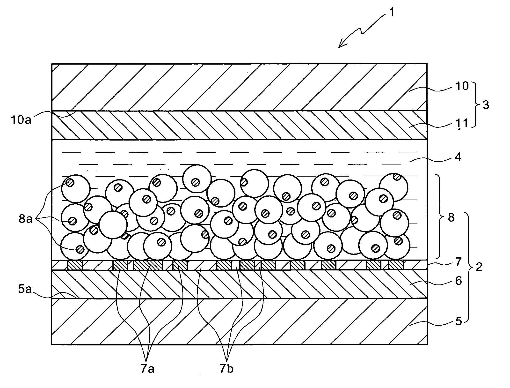
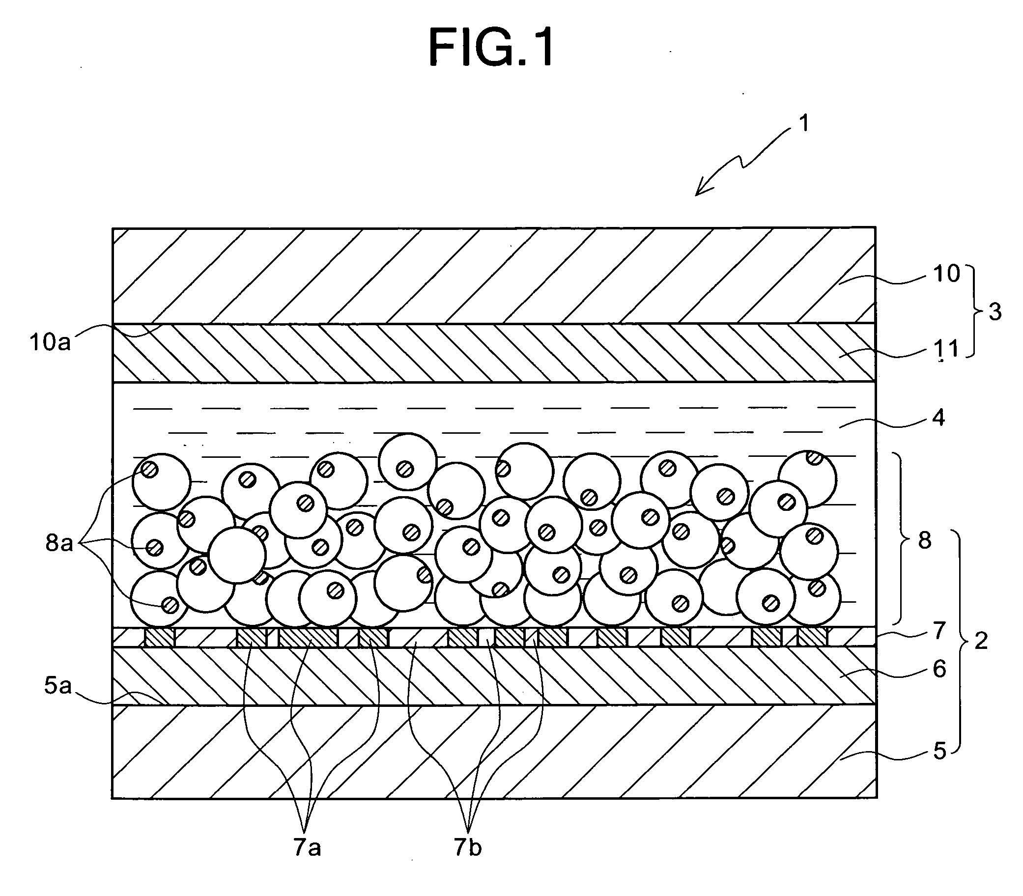
[0012] According to the present invention, a composite film comprising a metal portion of titanium or the like and an oxide portion of titanium oxide or the like (a transparent portion of an oxide) is formed on a transparent electrode film. The contact (the contact of a metal with a semiconductor) of the metal portion of the composite film with a porous semiconductor electrode film of titanium oxide or the like serves as a Schottky contact which provides rectification characteristics. In addition, a portion of the composite film, which does not contact the porous semiconductor electrode film, is a transparent oxide portion. Thus, it is possible to prevent the quantity of light for photoelectric transfer from decreasing. That is, in the metal portion of the composite film, electrons are easy to move from the porous semiconductor film toward the transparent electrode, whereas electrons are difficult to move in the reverse direction thereof. Thus, it is possible to prevent the reverse movement of electrons from the transparent electrode film to the semiconductor layer, and it is possible to decrease the probability of recombination of electrons with dye. In addition, it is possible to decrease the quantity of light for photoelectric transfer in the transparent oxide portion of the composite film, so that it is possible to improve the power generation efficiency of the solar cell.
[0013] According to the present invention, it is possible to provide a photoelectrode substrate for a dye sensitizing solar cell capable of preventing the reverse movement of electrons from a transparent electrode film of the photoelectrode substrate of the cell to a semiconductor layer thereof and preventing the quantity of light for photoelectric transfer from decreasing to improve the power generation characteristics of the cell.

Problems solved by technology

Conventional dye sensitizing solar cells are not intended for practical use since they have a low photoelectric transfer efficiency.
Therefore, the residence time of electrons in the porous semiconductor electrode film 108 is increased, so that there is a problem in that the probability of recombination of the electrons with the dye is increased to deteriorate the power generation characteristics of the dye sensitizing solar cell 101.

Method used


Image

  • Photoelectrode substrate of dye sensitizing solar cell, and method for producing same
  • Photoelectrode substrate of dye sensitizing solar cell, and method for producing same
  • Photoelectrode substrate of dye sensitizing solar cell, and method for producing same

Examples


example

[0041] An example of a photoelectrode substrate for a dye sensitizing solar cell and a method for producing the same according to the present invention will be described below in detail.

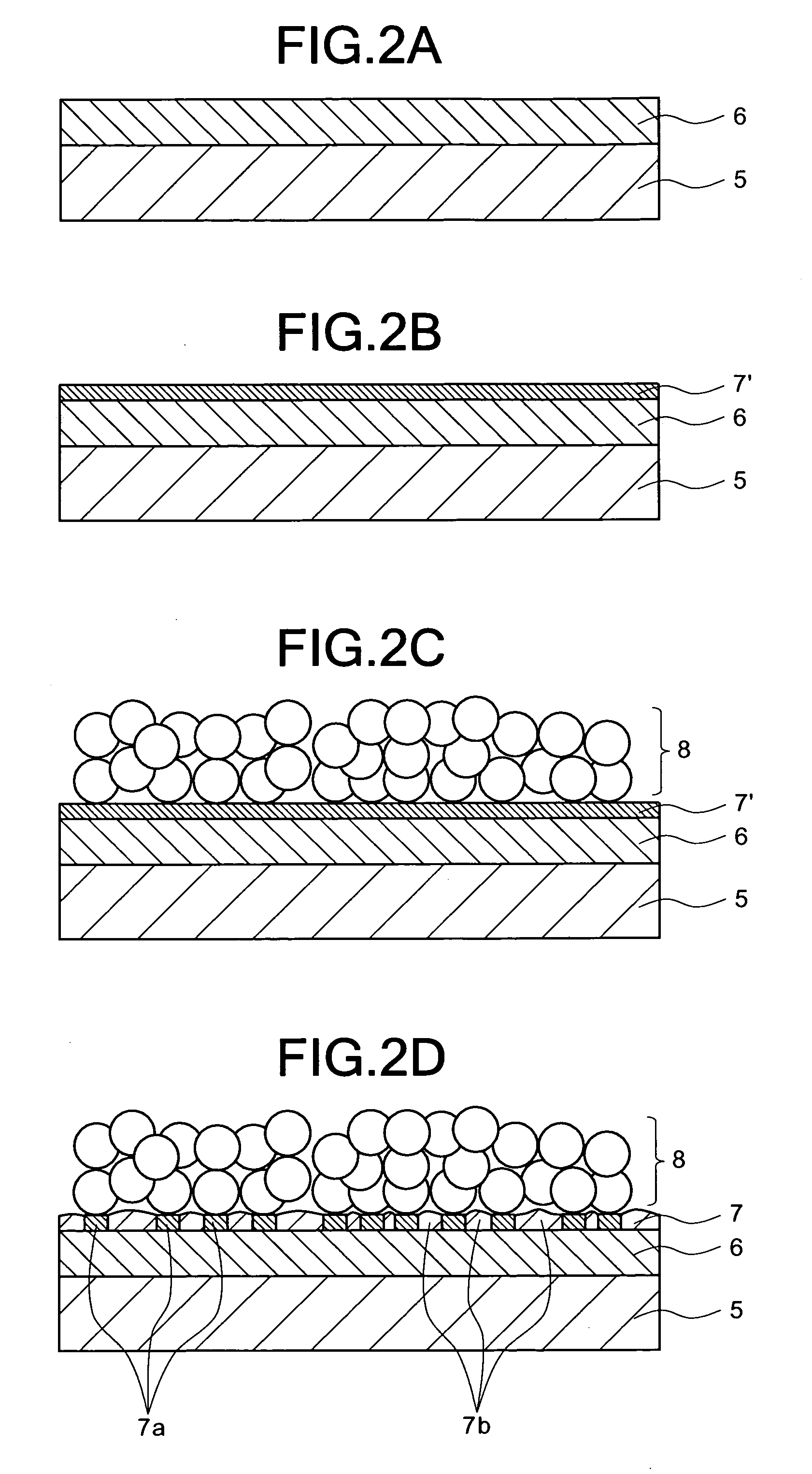
[0042] First, there was prepared a substrate member with ITO film wherein a transparent electrode film of ITO (ITO film) 6 was formed on the surface of a substrate member 5 of polyethylene naphthalene (PEN) (the plate member having a rectangular planar shape, each side having a length of 5 cm, and the plate member having a thickness of 125 μm and a value of electric resistance of 10Ω / □) (see FIG. 2A). The substrate member with ITO film, together with titanium serving as a target material, was arranged in a vacuum device into which argon gas was fed at 50 sccm. Then, a sputtering process using plasma produced on the surface of the target material by a high-frequency discharge (13.56 MHz, 400 W) was carried out for sixty seconds to form a metal film (titanium film) 7′ having a thickness of 10 nm on th...


PUM


Abstract

In a dye sensitizing solar cell 1 wherein an electrolyte 4 is filled in a space between a photoelectrode substrate 2 and a counter electrode of a counter electrode substrate 3, a composite film 7 comprising metal portions 7a of titanium or the like and oxide portions 7b thereof is formed on a transparent electrode film 6 formed on the surface of a substrate member 5, and a porous semiconductor electrode film 8 adsorbing or carrying sensitizing dyes 8a thereon is formed on the composite film 7, the metal portions 7a of the composite film 7 contacting the porous semiconductor electrode film 8, and the oxide portions 7b of the composite film 7 contacting the electrolyte 4 without contacting the porous semiconductor electrode film 8.

Description

BACKGROUND OF THE INVENTION [0001] 1. Field of the Invention [0002] The present invention relates to a photoelectrode substrate for a dye sensitizing solar cell, and a method for producing the same. More specifically, the invention relates to a photoelectrode substrate for a dye sensitizing solar cell wherein an electrolyte is filled in a space between a counter electrode of a counter electrode substrate and the photoelectrode substrate, and a method for producing the same. [0003] 2. Description of the Prior Art [0004] In recent years, from the point of view of environmental issues, solar cells for converting light energy to electric energy have been widely noticed. In particular, dye sensitizing solar cells have been widely noticed since the costs for producing them can be low. Conventional dye sensitizing solar cells are not intended for practical use since they have a low photoelectric transfer efficiency. Recently, there has been developed a technique for using a porous semicond...

Claims


Application Information

Patent Timeline
IPC IPC(8): H01L31/00
CPCH01G9/2031Y02E10/542H01G9/2095
Inventor MIYOSHI, KOZO
Owner ENPLAS CORP
Learn More