Connector and portable cable

a technology of connecting wires and portable cables, applied in the direction of coupling parts engagement/disengagement, coupling device connection, electrical equipment, etc., can solve the problems of conduction failure or short-circuit, cracks or fractures, and the strength of the connection is likely to decrease, so as to achieve high precision engagement, reduce the accuracy of fitting walls into the insertion groove, and easy to design

Inactive Publication Date: 2007-02-01
KYOCERA ELCO CORP
View PDF13 Cites 3 Cited by
  • Summary
  • Abstract
  • Description
  • Claims
  • Application Information

AI Technical Summary

Benefits of technology

[0021] According to the present invention, since the engaging projection or the engaging recess can be formed without affecting the shape of the insertion groove designed taking into account the clearance for fitting, the fitting accuracy of the fitting wall into the insertion groove is not reduced. Furthermore, since the shapes of the engaging projection and the engaging recess can be designed independently of the design of the insertion groove, the engaging projection and the engaging recess can be easily designed in a shape which provides high precision engagement with each other. Moreover, since the engaging projection is formed on the bottom surface of the fitting recess, the projection can be formed so as to have a larger height in the fitting direction. In addition, since the engaging recess is formed on the surface of the fitting projection, the engaging recess can be formed so as to have a larger depth in the fitting direction. Therefore, the contact area between the engaging recess and the engaging projection can be increased. Hence, the reduction in the profile height can be achieved in the above-described manner. In addition, if an impact caused by dropping or the like is applied to the connector, the load or external force is easily dispersed, and the fit between the receptacle connector and the plug connector can be maintained. Furthermore, the occurrence of cracks or fractures can be prevented, and the connector can be manufactured efficiently.

Problems solved by technology

However, since the profile height and size of such a connector are reduced, the strength thereof is likely to decrease.
Thus, even after the plug connector is fitted into the receptacle connector or after these connectors are mounted on respective substrates, cracks or fractures may occur if a load or external force caused by dropping, an impact, or the like is applied.
This may cause conduction failure or short-circuit depending on the extent of the external force.
Furthermore, since it is difficult to machine a mold for use in injection molding, it is difficult to accurately form the rectangular shapes of the fitting recess and the fitting projection, and thus the fitting projection may not be able to be fitted correctly into the fitting recess.
Furthermore, since the fitting recess and the fitting projection are fitted together in the fitting groove, they are subjected to twist, rotation, or other movements due to the clearance necessary for fitting the socket into the header.
In addition, since the abutment area of the fitting recess against the fitting projection is small upon impact caused by dropping, or the like, the applied load or external force cannot be sufficiently dispersed.
Therefore, the occurrence of cracks or fractures cannot be satisfactorily prevented.

Method used


Image

  • Connector and portable cable
  • Connector and portable cable
  • Connector and portable cable

Examples


Embodiment Construction

[0041] Hereinafter, embodiments of the present invention will be described in detail with reference to the drawings.

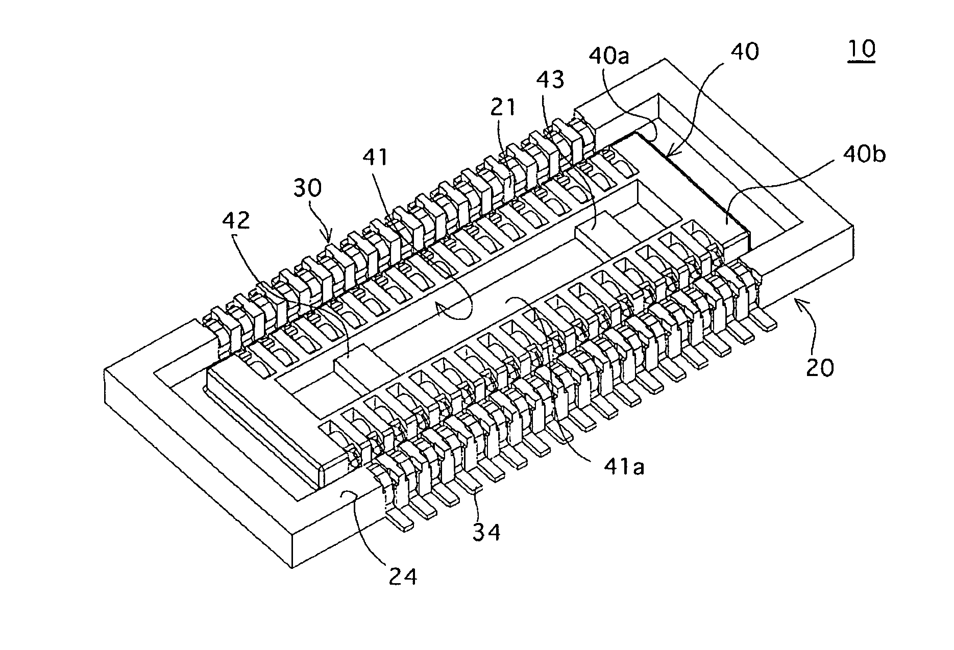
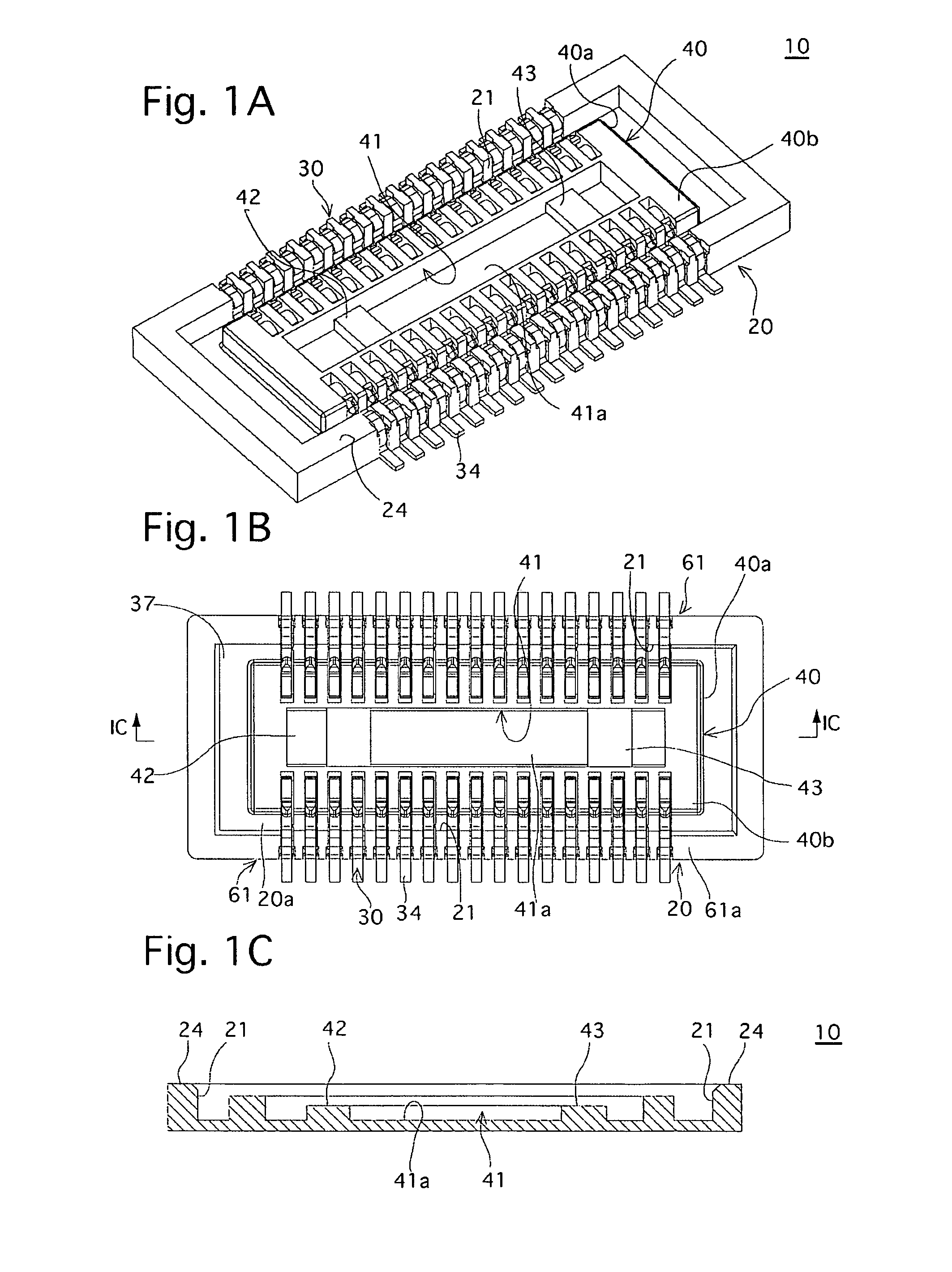
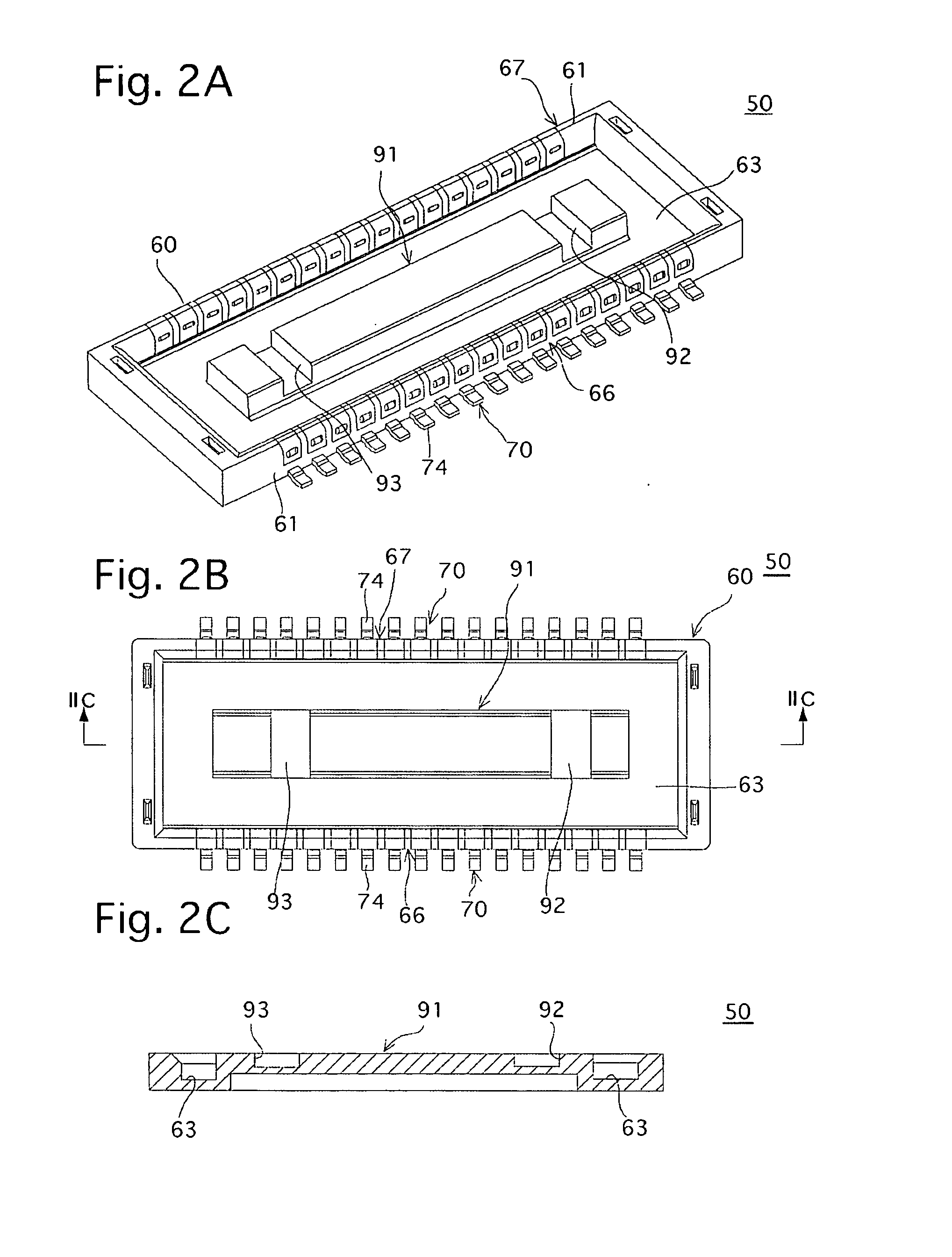
[0042] The connector according to the first embodiment is composed of a receptacle connector 10 (FIG. 1) and a plug connector 50 (FIG. 2) which are mated with each other (fitted together) to establish an electrical connection. For example, one of the receptacle connector 10 and the plug connector 50 is mounted on the substrate of an LCD (a liquid crystal display) unit (display device) or a CCD (a charge-coupled device) unit (imaging device). The other of the receptacle connector 10 and the plug connector 50 is placed on a substrate which is electrically connected to the unit to control the operation thereof. By mating the receptacle connector 10 with the plug connector 50, the unit is electrically connected with the substrate. The plug connector 50 and the receptacle connector 10, according to the illustrated embodiment, are applicable for providing connections within...


PUM


Abstract

A connector includes a first connector provided with a first insulating member and a first contact, and a second connector provided with a second insulating member and a second contact which is electrically connected with the first contact by fitting the first and second insulating members together. A fitting projection is provided in one of the first and second insulating members so as to project toward the other of the first and second insulating members. A fitting recess, into which the fitting projection is fitted when the first and second insulating members are fitted, is provided in the other of the first and second insulating members. The fitting projection includes an engaging recess which extends entirely across the fitting projection in one direction. The fitting recess includes an engaging projection which is engaged with the engaging recess when the first and second insulating members are fitted together.

Description

CROSS REFERENCE TO RELATED APPLICATION [0001] The present invention is related to and claims priority of the following pending application, namely, Japanese Patent Application No. 2005-218982 filed on Jul. 28, 2005. BACKGROUND OF THE INVENTION [0002] 1. Field of the Invention [0003] The present invention relates to a connector having a receptacle connector and a plug connector which are mated with each other to establish electrical connection, and also relates to a portable terminal provided with such a connector. [0004] 2. Description of the Related Art [0005] In a connector which has a receptacle connector and a plug connector mounted on respective substrates, and in which the receptacle and plug connectors are electrically connected to each other by inserting the plug connector into an insertion groove provided in the receptacle connector, there has been increasing demand for miniaturization. Specifically, since a portable terminal or other devices on which the connector is mount...

Claims


Application Information

Patent Timeline
Patent Type & Authority Applications(United States)
IPC IPC(8): H01R13/62H01R12/71H01R12/62
CPCH01R12/716H01R13/642H01R13/631
Inventor SHIROYAMA, YUUSUKE
Owner KYOCERA ELCO CORP
Why Eureka
Try Eureka