
Method and apparatus for syringe-based sample introduction within a flow cytometer

Inactive Publication Date: 2007-02-01
BECKMAN COULTER INC
View PDF41 Cites 56 Cited by
  • Summary
  • Abstract
  • Description
  • Claims
  • Application Information

AI Technical Summary

Benefits of technology

[0011] A first object of the present invention is to provide a sample introduction apparatus for a flow cytometer that has the advantages of utilizing fewer components and occupying less space than are required within a conventional flow cytometer sample introduction apparatus. A second object of the present invention is to provide a sample introduction apparatus for a flow cytometer that has the advantage of reducing the opportunities for specimen contamination relative to conventional flow cytometer sample introduction apparatus. Another object of the present invention is to provide a sample introduction apparatus for a flow cytometer that has the advantages of increasing analytical efficiency and reducing preparation or set up time in relation to conventional flow cytometer sample introduction apparatus. Yet another object of the present invention is to provide a flow cytometer having an improved sample introduction apparatus that incorporates one or more of the advantages described above. A still further object of the present invention is to provide a method of sample introduction to a flow cytometer that provides one or more of the advantages described above.

Problems solved by technology

A known problem in the use of conventional flow cytometers arises from cross contamination between successive sample substances and contamination from non-sterile instrument parts.
The above-described precautions that must be undertaken to prevent the contamination of an analyzed substance or to prevent cross contamination between substances can decrease the overall usage efficiency of a conventional flow cytometer.
The exercise of these contamination precautions can also delay the start of and increase the costs of analyses obtained from the conventional flow cytometer.
Thus, inefficiencies in analytical capabilities can have detrimental health consequences for patients.
Each such transfer creates new opportunities for contamination or possible spoilage of the sample.

Method used


Image

  • Method and apparatus for syringe-based sample introduction within a flow cytometer
  • Method and apparatus for syringe-based sample introduction within a flow cytometer
  • Method and apparatus for syringe-based sample introduction within a flow cytometer

Examples


Embodiment Construction

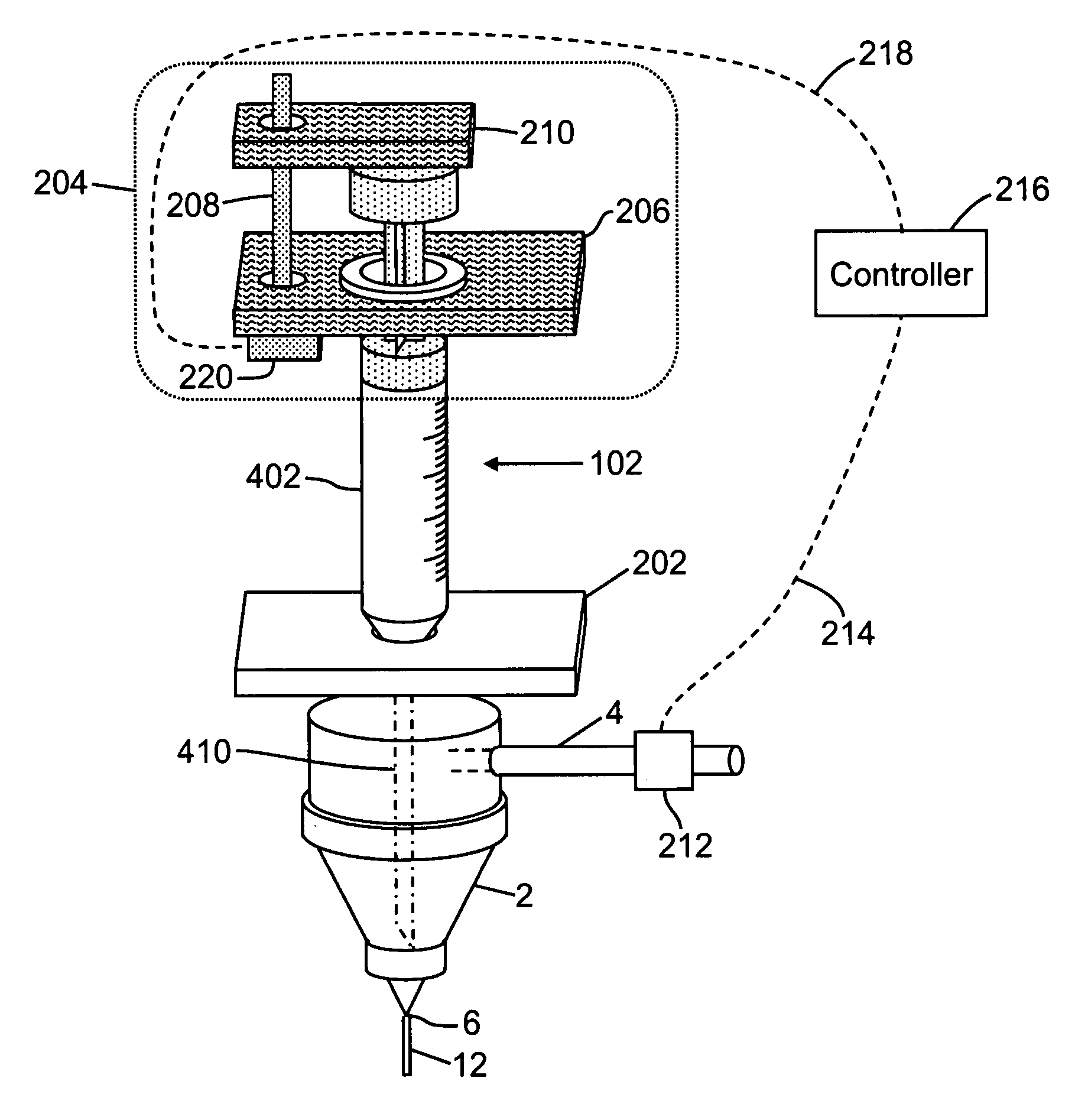
[0020] The present invention relates to an improved method and apparatus for sample introduction into a flow cytometer. The following description is presented to enable one of ordinary skill in the art to make and use the invention and is provided in the context of a patent application and its requirements. Various modifications to the preferred embodiments will be readily apparent to those skilled in the art and the generic principles herein may be applied to other embodiments. Thus, the present invention is not intended to be limited to the embodiments shown but is to be accorded the widest scope consistent with the principles and features described herein. To more particularly appreciate the features and advantages of the method and apparatus of the present invention, the reader is referred to the appended FIGS. 3-6 in conjunction with the following discussion.

[0021]FIG. 3 is a schematic drawing of a first preferred embodiment of a sample introduction apparatus for a flow cytome...


PUM


Abstract

An apparatus for introducing a specimen into a flow cytometer comprises: a syringe having a hollow barrel containing the specimen, a plunger partially within the barrel and a needle that extends into a volume of a nozzle of the flow cytometer; a one-way port in the nozzle forming a seal against the needle; a mounting platform coupled to both the syringe and to the flow cytometer; and a syringe pump coupled to the plunger, the syringe pump comprising a motor, a drive mechanism coupled to the motor; and a clamping mechanism coupled to the drive mechanism, wherein the motor operates the drive mechanism so as to cause the clamping mechanism to depress the plunger into the barrel.

Description

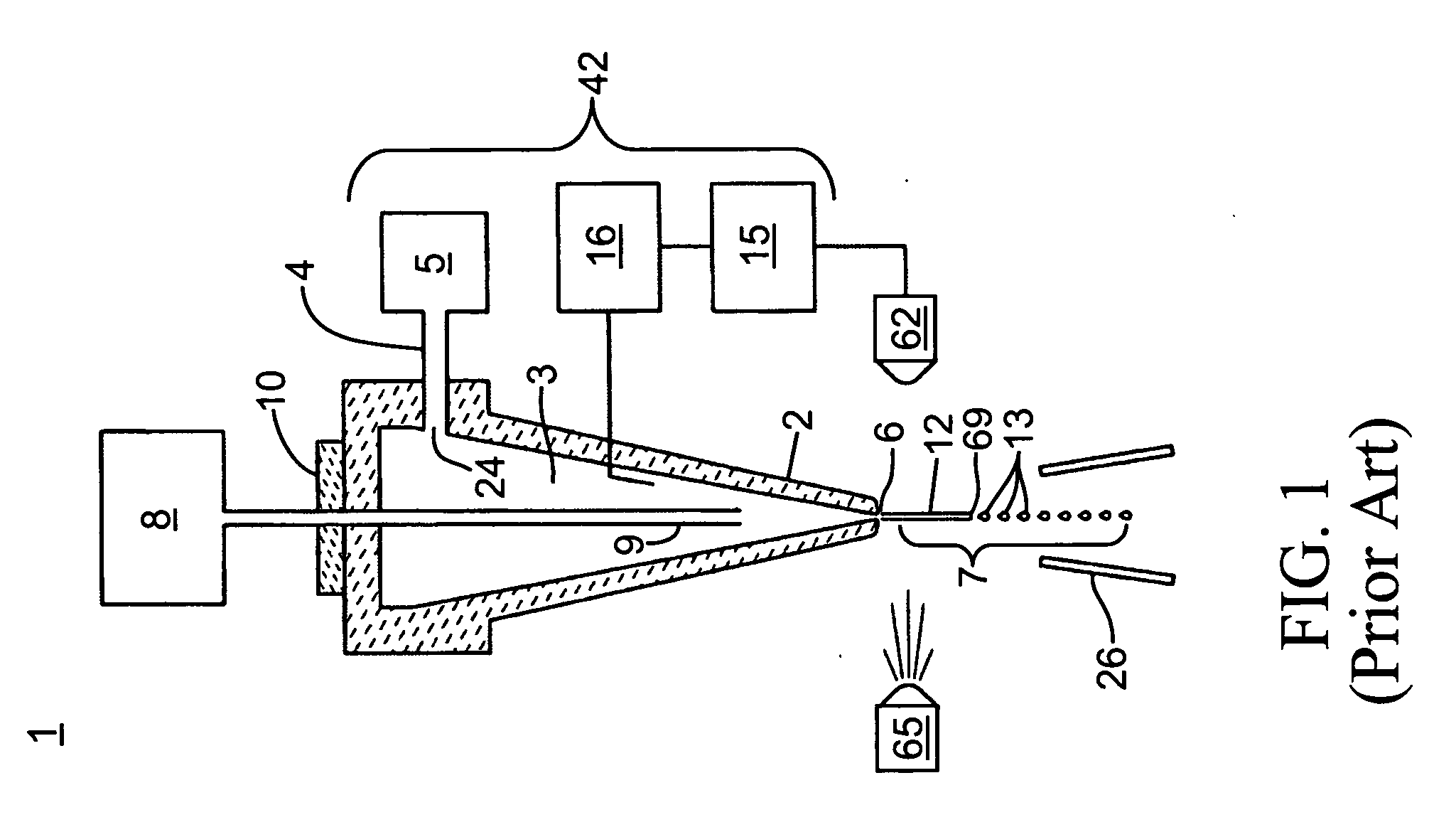
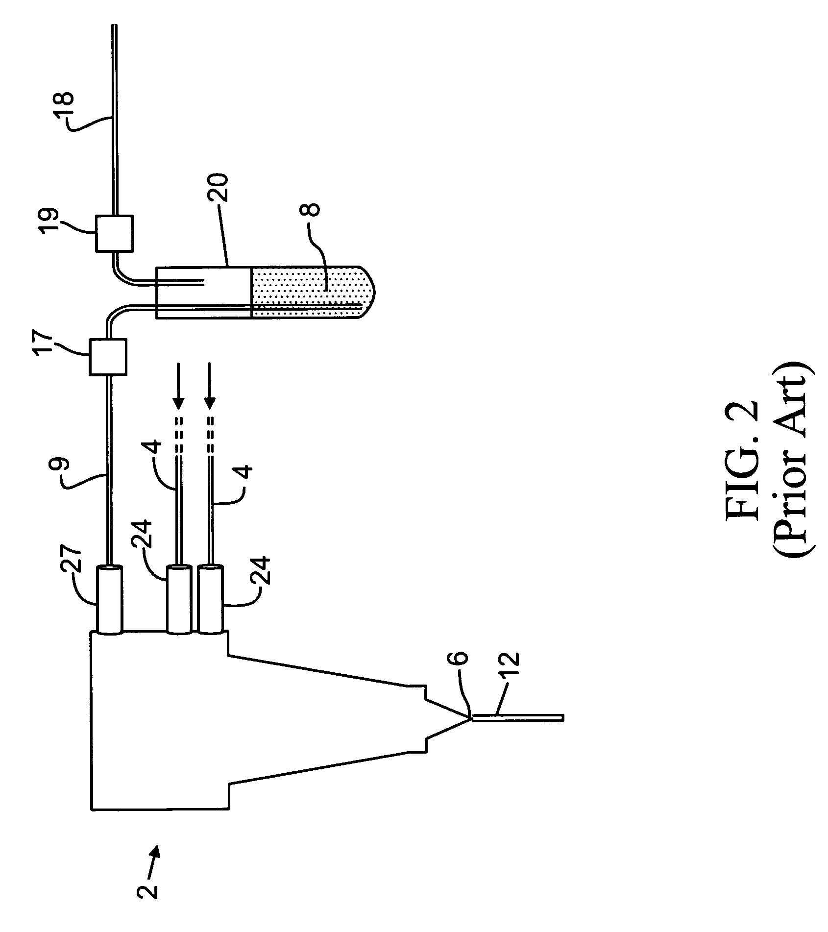
FIELD OF THE INVENTION [0001] The present invention relates to flow cytometers and flow cytometry for analyzing and sorting individual particles. More particularly, the present invention relates to sample introduction apparatus for a flow cytometer, the sample introduction apparatus including a syringe directly coupled to the flow cytometer. BACKGROUND OF THE INVENTION [0002] Flow cytometers have been in clinical and research use for many years. Basically, the systems act to position small amounts of a substance within a sheath fluid. This sheath fluid may either form droplets or may exist in a stream for optical analysis. Through hydrodynamic focusing and laminar flow, the sample is forced into a single file of individual cells and the like and is surrounded by a sheath fluid. In many applications, the sheath fluid together with its entrained substance exits a nozzle in a jet and either free falls or is channeled in an optically transparent pathway for analysis. Analysis and possib...

Claims


Application Information

Patent Timeline
IPC IPC(8): G01N33/00
CPCG01N2015/1409G01N35/1095G01N15/1409
Inventor VANDERGAW, ANGELA L.
Owner BECKMAN COULTER INC
Learn More