
Submerged rotor electric water pump with structural wetsleeve

Active Publication Date: 2014-01-16
HANON SYST EFP CANADA LTD
View PDF8 Cites 60 Cited by
  • Summary
  • Abstract
  • Description
  • Claims
  • Application Information

AI Technical Summary

Benefits of technology

The present invention provides a pump with a low magnetic air gap between the rotor and stator, making it a smaller and lighter pump that can fit in smaller spaces. It also has fewer components, high efficiency, and low noise and vibration levels. The invention includes a way to cool the pump using a thermal medium, which makes it easier to package.

Problems solved by technology

However, the use of rare earth metals may be damaged by the fluid such that the rare earth metals may require additional packaging so that damage is prevented.

Method used


Image

  • Submerged rotor electric water pump with structural wetsleeve
  • Submerged rotor electric water pump with structural wetsleeve
  • Submerged rotor electric water pump with structural wetsleeve

Examples


Embodiment Construction

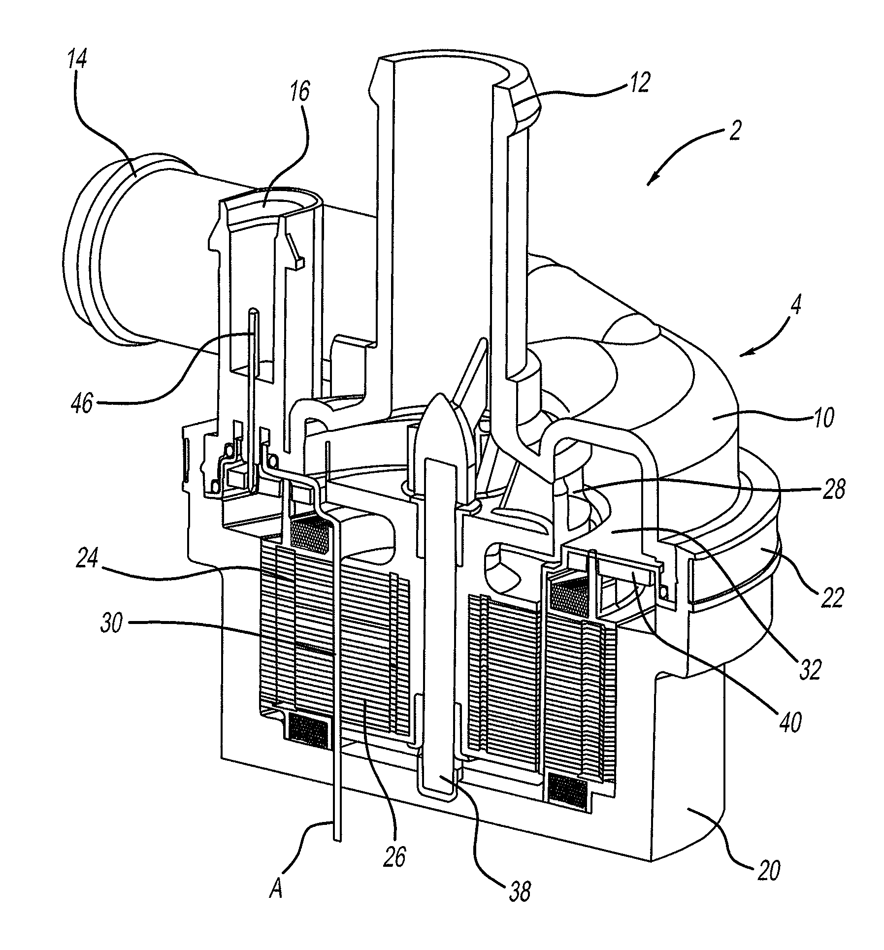
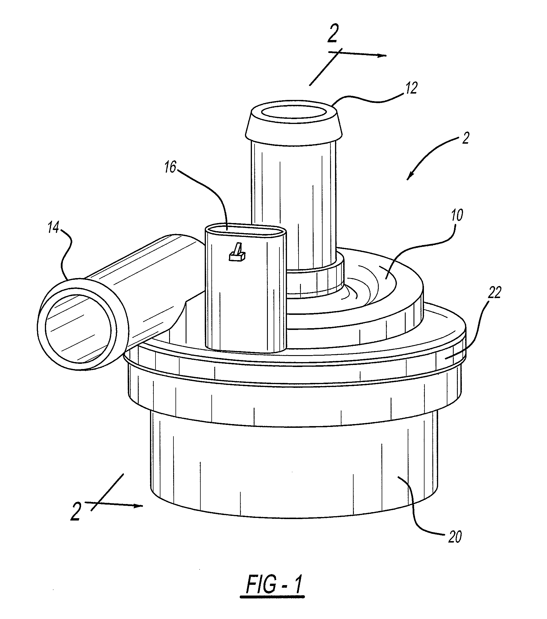
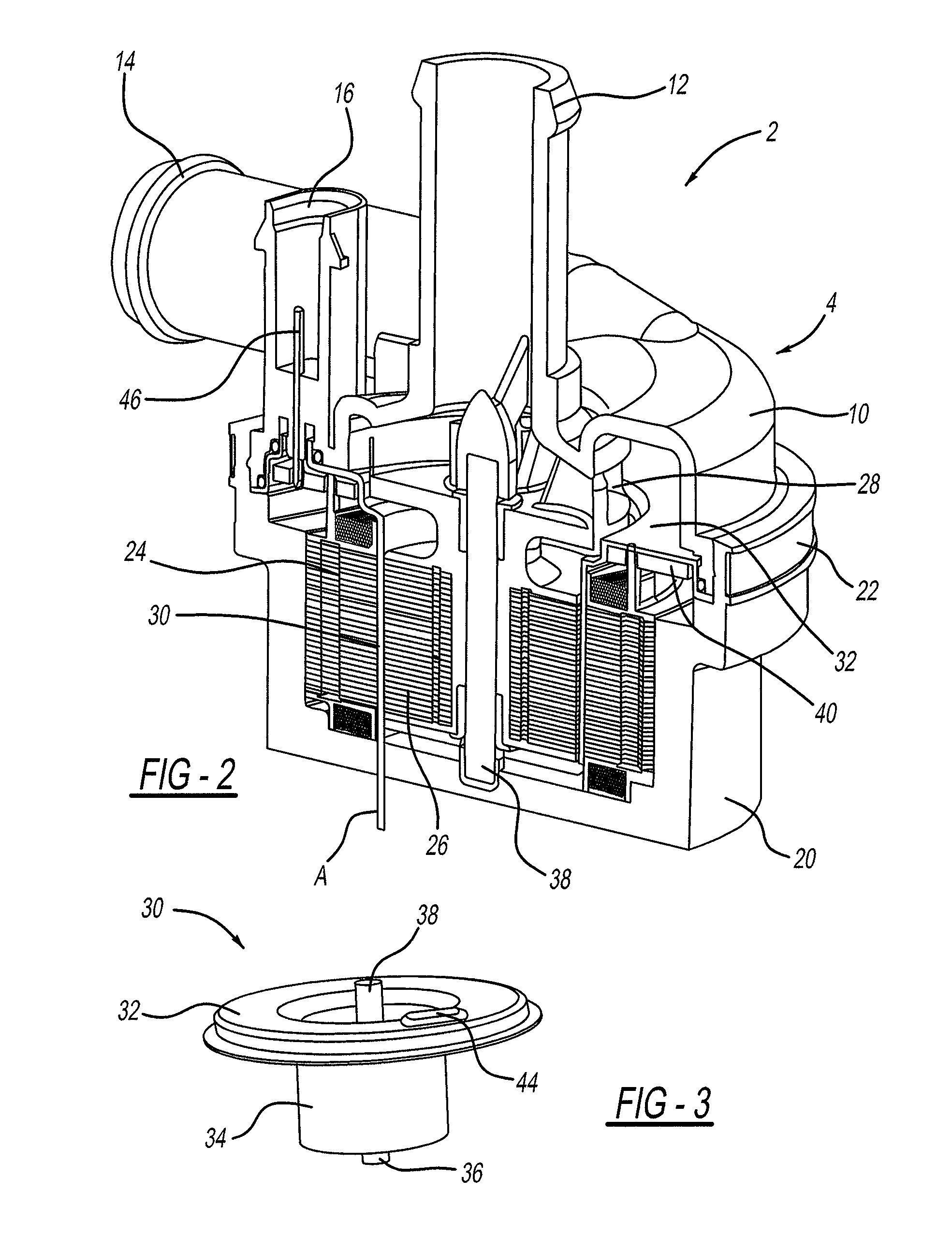
[0022]Referring in general to all of the figures, the present disclosure and teachings described herein provide for a housingless water pump (hereinafter “pump”) that is utilized as part of an engine cooling system. The pump may be any pump that moves a fluid. The pump may move air, water, anti-freeze, coolant, or a combination thereof. The pump may operate using any automotive voltage. The pump taught herein may use about 10 watts or more, about 15 watts or more, about 20 watts or more, or about 25 watts or more to operate. The pump may operate using about 50 watts or less, about 45 watts or less, about 40 watts or less, or about 35 watts or less.

[0023]The pump includes a rotor and a stator. The rotor and stator are separated by a wetsleeve. The stator may be any stator that assists in rotating a rotor so that a fluid is moved. The stator may be any configuration so that the stator rotates a rotor and assists in moving a fluid. The stator includes one or more coils. The coil may be...


PUM

PropertyMeasurementUnit
Lengthaaaaaaaaaa
Poweraaaaaaaaaa

Abstract

An electric pump comprising: a rotor, a wet sleeve surrounding the rotor; and a stator surrounding the wet sleeve and the rotor; wherein the rotor and stator have a magnetic air gap of about 2 mm or less.

Description

CROSS-REFERENCE TO RELATED APPLICATIONS[0001]This application claims the benefit of U.S. Provisional Application No. 61 / 672,044 filed Jul. 16, 2012.FIELD OF THE INVENTION[0002]The present invention relates to an improved electric water pump, and more specifically an electric water pump having an improved wet sleeve so that the water pump is free of a housing.DISCUSSION OF RELATED ART[0003]Generally, water pumps include a stator and rotor. The rotor is in communication with an impeller for moving a fluid. The fluid enters the pump through an inlet in a volute, contacted with an impeller and moved through an outlet in the volute. The rotor and stator are contained with a housing that connects with the volute. Generally, the rotor and stator are separated by a magnetic air gap and the rotor and stator include rare earth metals so that magnetic air gap between the rotor and stator may be bridged so that the rotor is rotated during use and so that the rotor, the stator, or both may be is...

Claims


Application Information

Patent Timeline
IPC IPC(8): F04D29/58
CPCF04D29/588F04D13/0606F04D13/0686F04D29/026F04D29/426F04D29/5813F05D2300/431F04D13/0626H02K5/128
Inventor MUIZELAAR, RICHARDGLOWACKI, NICHOLAS J.WANG, LIPINGMORITZ, DAVE A.MILLS, KYLELAKERDAS, ANDREW
Owner HANON SYST EFP CANADA LTD
Learn More