
Time synchronizing method and apparatus based on time stamp

a time synchronization and time stamp technology, applied in data switching networks, multiplex communication, digital transmission, etc., can solve the problems of large dpll noise generation, phase errors can accumulate, and excessive siz

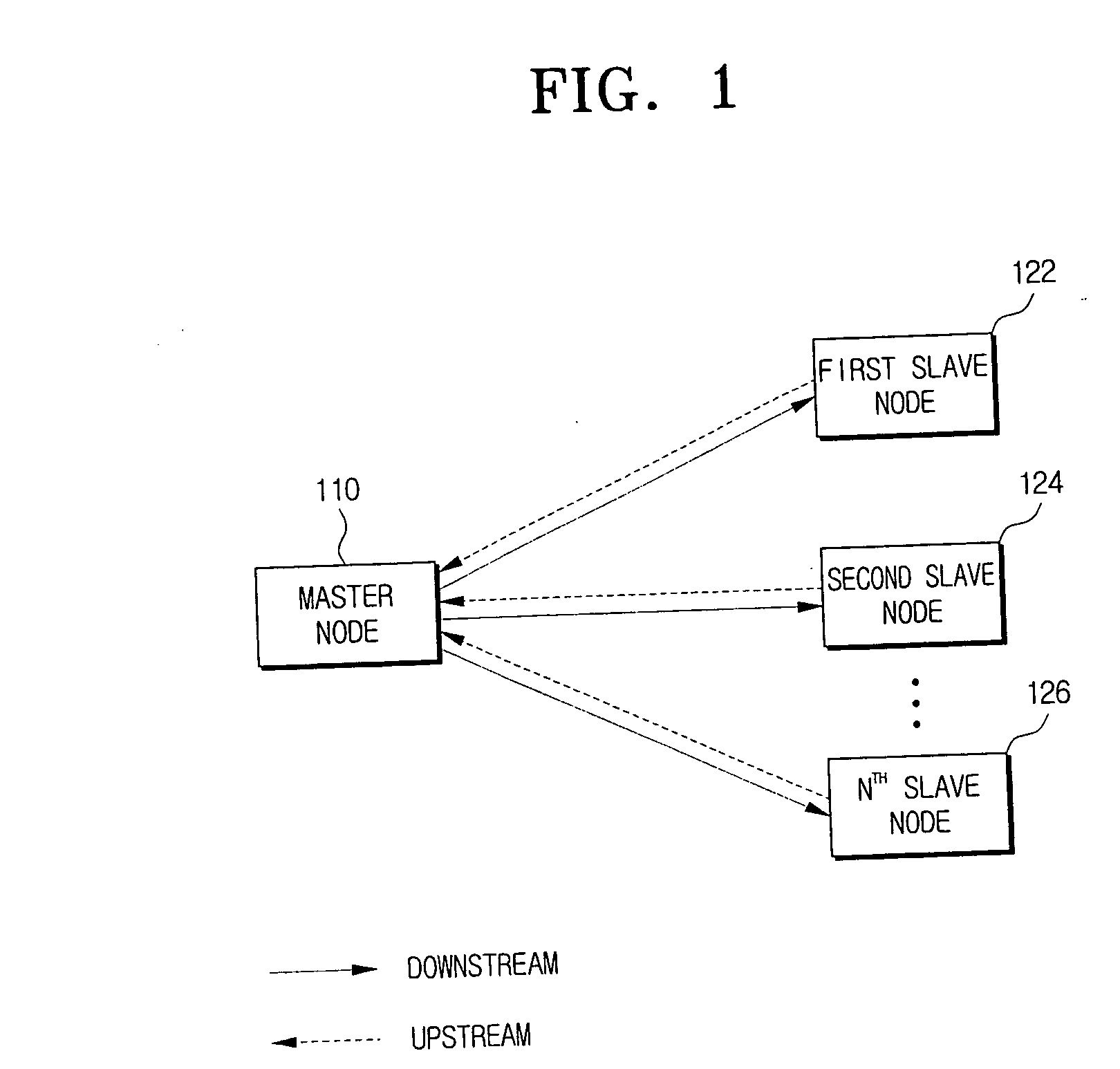
Inactive Publication Date: 2007-02-01
SAMSUNG ELECTRONICS CO LTD
View PDF5 Cites 58 Cited by
  • Summary
  • Abstract
  • Description
  • Claims
  • Application Information

AI Technical Summary

Benefits of technology

[0059] As described above, according to the present invention, synchronizing can be achieved in a filtering way using a time stamp in a packet switching network. Thus, a PLL does not need to be used. Also, a high-priced oscillator preventing an increase in an error does not need to be used. In addition, jitter and wander of timing can be reduced.

Problems solved by technology

Also, downstream clocks may synchronize with a clock of the master node but may vary due to propagation delays of the downstream clocks.
Also, the first and second ways do not specify whether time stamps are based on the free-running local clock values or the corrected values based on corrections due to previous time stamps.
For example, if y is 100 ppm and T is 10 ms, the maximum phase is 2000 ns; this is excessively large for some applications, e.g., digital video and audio transport in Residential Ethernet (i.e., Audio / Video Bridging Network).
In cases where time stamps are used to adjust DCOs that are part of digital phase-locked loops (DPLLs), phase errors can accumulate as timing is transferred over a chain of nodes.
For a DCO with given inherent noise level, a narrower bandwidth will result in larger DPLL noise generation.
However, use of DPLL structures with smaller gain peaking results in a more sluggish DPLL and the need for a more stable, i.e., lower noise, oscillator.
Accordingly, a conventional time synchronizing method is based on larger jitter and wander accumulation or acceptable jitter and wander accumulation but possibly at the cost of a lower noise and therefore more expensive oscillator.

Method used


Image

  • Time synchronizing method and apparatus based on time stamp
  • Time synchronizing method and apparatus based on time stamp
  • Time synchronizing method and apparatus based on time stamp

Examples


Embodiment Construction

[0032] Certain embodiments of the present invention will be described in greater detail with reference to the accompanying drawings.

[0033] In the following description, the same drawing reference numerals are used for the same elements even in different drawings. Certain matters described herein, such as construction details and other elements are merely provided to assist in a comprehensive understanding of the invention. Thus, it is apparent that the present invention can be carried out without those described matters. Also, well-known functions or constructions are not described in detail since that would obscure the invention in unnecessary detail.

[0034] A time stamp used for synchronizing will be described to assist in an understanding of the present invention.

[0035] In one approach, a time stamp is expressed in a count state of a rising 32-bit binary counter and determined by a local free-running clock of 10.24 MHz of a master or slave node. In a second approach, a time sta...


PUM


Abstract

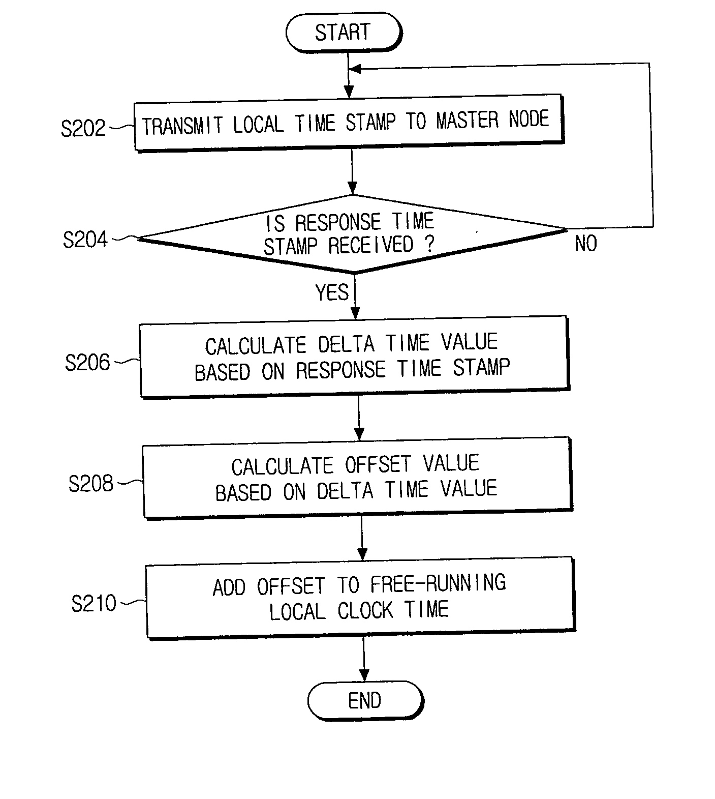
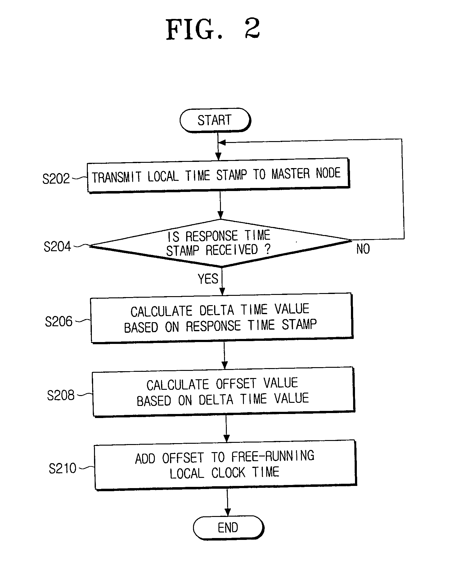
Provided are a time synchronizing method and apparatus based on a time stamp. The time synchronizing method includes: transmitting a local time stamp based on a free-running local clock to a master node; receiving a response time stamp from the master node; calculating a delta time value based on the response time stamp; filtering the delta-time using a digital low pass filter running at the free-running local clock rate; and adjusting a local clock time based on the filtered delta time value.

Description

CROSS-REFERENCE TO RELATED APPLICATIONS [0001] This application claims the benefit under 35 U.S.C. § 119(a) of U.S. Provisional Patent Application No. 60 / 699,389, filed in the USPTO on July 15, 2005, and claims priority from Korean Patent Application No. 2006-58479, filed in the Korean Patent Office on Jun. 28, 2006, the entire disclosures of which are incorporated herein by reference.BACKGROUND OF THE INVENTION [0002] 1. Field of the Invention [0003] Methods and apparatuses consistent with the present invention relate to time synchronizing based on a time stamp in a packet switching network, and an aspect of the invention relates to a time synchronizing method and apparatus based on a time stamp by which a delta time value and an offset value are calculated and filtered through a loop filter based on the time stamp received from a master node to a slave node to adjust a local clock time based on the delta time value and the offset value so as to synchronize a local clock of the sla...

Claims


Application Information

Patent Timeline
IPC IPC(8): H04L7/00
CPCH04L12/2803H04J3/0667H04L7/00H04J3/06
Inventor RYU, HYUN-SURKGARNER, GEOFFREY M.FENG, FEI FEIDEN HOLLANDER, CORNELIS JONANNIS
Owner SAMSUNG ELECTRONICS CO LTD
Learn More