Thermal type flow measuring apparatus

Active Publication Date: 2007-02-01
HITACHI ASTEMO LTD
View PDF1 Cites 0 Cited by
  • Summary
  • Abstract
  • Description
  • Claims
  • Application Information

AI Technical Summary

Benefits of technology

[0009] It is an object of the present invention to provide a thermal type air flow meter that can reduce the soiling of a heating resistor and, at the same time, reduce a measurement error caused by aging deterioration even under a severe environmental condition, such as an idling driving state after high-load driving, without complicating the structure of the circuit and the sensor.
[0011] According to the present invention, it is possible to keep the heating temperature of the heating resistor low in the idling driving state, to increase the heating temperature as the air flow becomes higher, to reduce the soiling of the heating resistor, and to reduce a change in the output characteristics caused by aging deterioration without complicating the structure of circuits and sensors.

Problems solved by technology

However, the technology disclosed in JP-B-6-63801 requires an additional correction circuit, making both the circuit configuration and the sensor structure complex.
However, because the sensitivity of the sensor is decreased in proportion to a drop in temperature when the heating temperature is lowered, even a slight aging deterioration in the heating resistor could greatly change the output characteristics.
Therefore, a change in the air flow characteristics caused by aging deterioration in the heating resistor cannot be suppressed.
In addition, the most severe temperature environmental condition occurs in an actual car when the temperature of the intake air is increased by the radiation heat of the engine and, because the air flow is low, the temperature of the heating resistor is increased, for example, when the car is idling after high-load driving such as high-speed driving or hill-climbing driving.

Method used


Image

  • Thermal type flow measuring apparatus
  • Thermal type flow measuring apparatus
  • Thermal type flow measuring apparatus

Examples


first embodiment

[0028] the present invention will be described with reference to FIG. 1 to FIG. 7.

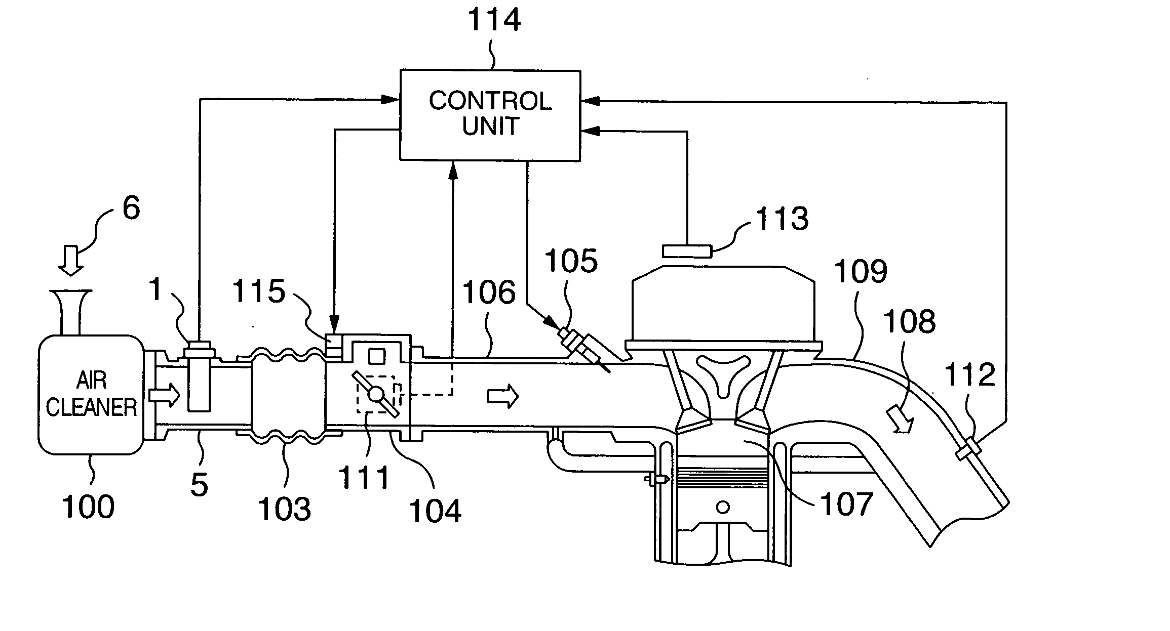
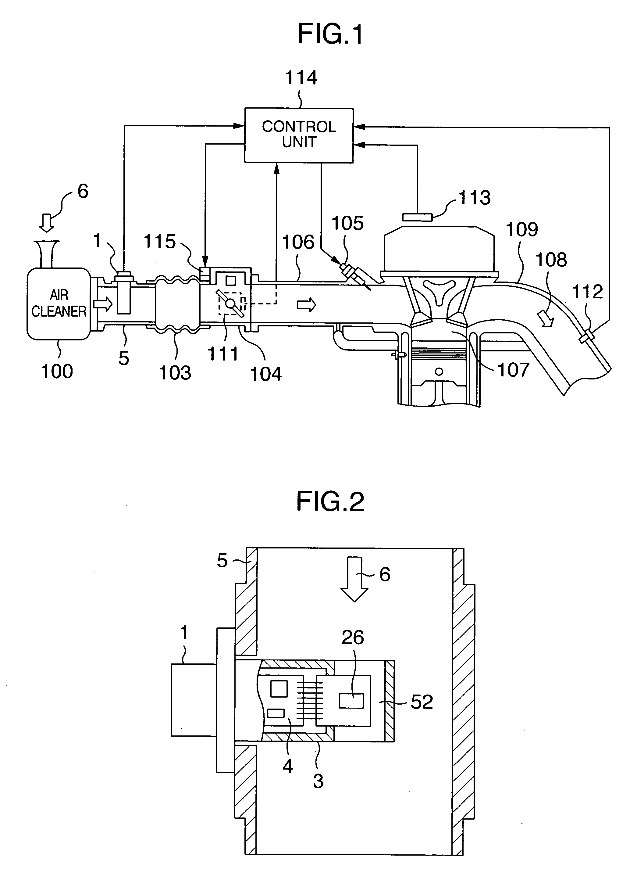
[0029]FIG. 1 is a diagram showing the general configuration of the main part of the operation control system of an internal combustion engine to which a thermal type air flow meter 1 in the first embodiment of the present invention is applied.

[0030] Referring to FIG. 1, intake air 6 taken in by an air cleaner 100 is supplied to an engine cylinder 107 via an intake manifold 106 comprising a main pipe 5 in which the thermal type air flow meter 1 is provided, an intake duct 103, a throttle body 104, and an injector (fuel injection valve) 105 to which fuel is supplied. Exhaust gas 108 produced by the engine cylinder 107 is exhausted externally via an exhaust manifold 109.

[0031] The thermal type air flow meter 1 is provided between the air cleaner 100 and the throttle body 104 in the engine room. An air flow signal output from the thermal type air flow meter 1, an intake air temperature signal, a throttle...

second embodiment

[0069] Next, the present invention will be described with reference to FIG. 8.

[0070]FIG. 8 is a diagram showing the wiring pattern of a thermal type air flow sensor element 26 in a thermal type air flow meter 1 in the second embodiment of the present invention.

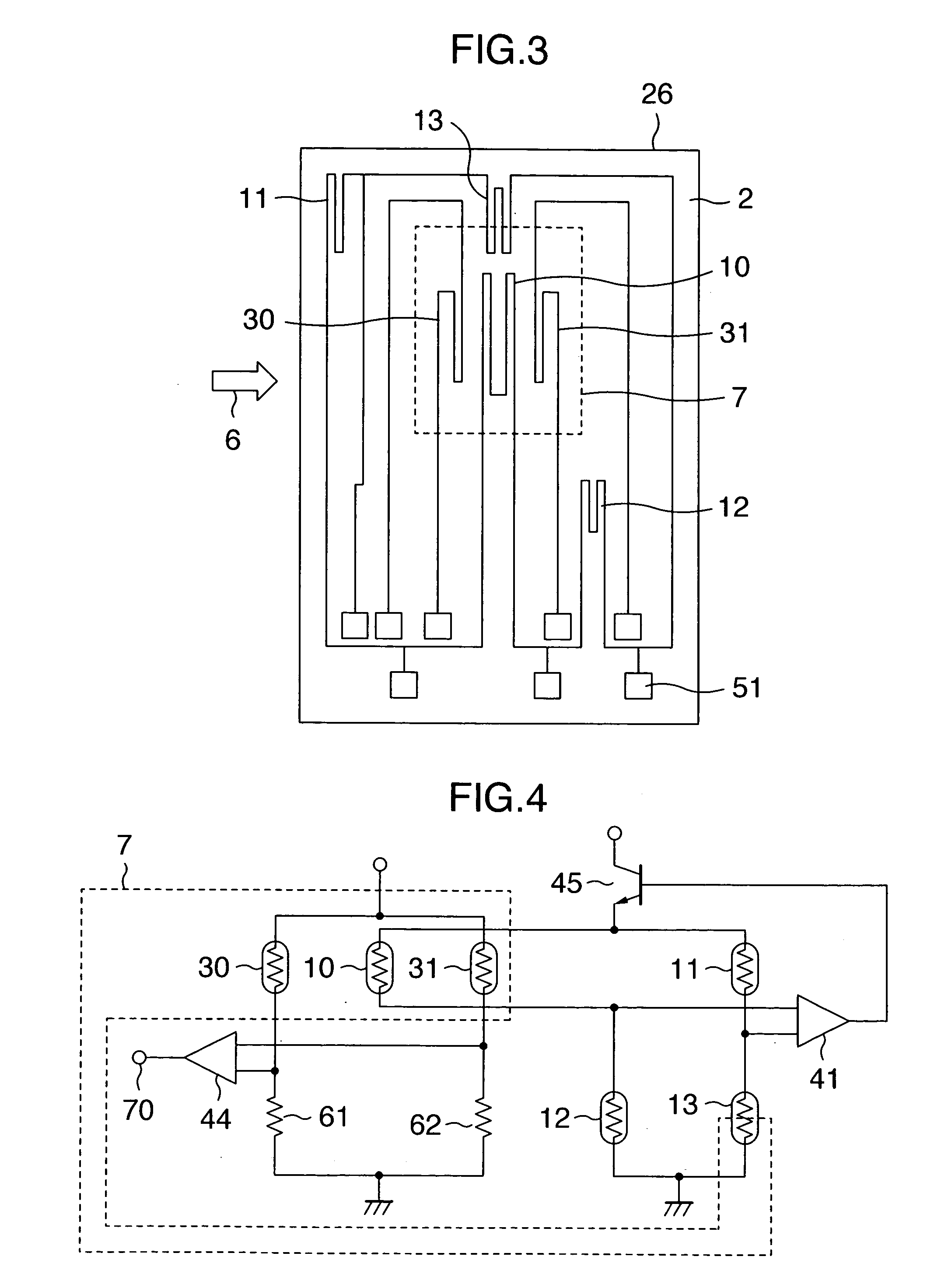
[0071] Referring to FIG. 8, the thermal type air flow sensor element 26 is structured in such a way that a part of a temperature sensitive resistor 13, positioned diagonally to a heating resistor 10 in the bridge circuit shown in FIG. 4, is positioned in the upstream side of a thin part 7 so that it is subject to the influence of the heat of the heating resistor 10. The rest of the structure is the same as that of the first embodiment of the present invention.

[0072] The temperature sensitive resistor 13 of the first embodiment of the present invention, shown in FIG. 3, is positioned approximately in the center between the upstream and the downstream in the same way as the heating resistor 10, while the temperature sensitive ...

third embodiment

[0075] the present invention will be described with reference to FIG. 9 and FIG. 10.

[0076]FIG. 9 is a diagram showing the wiring pattern of a thermal type air flow sensor element 26 in a thermal type air flow meter 1 in the third embodiment of the present invention.

[0077] Referring to FIG. 9, the thermal type air flow sensor element 26 comprises a semiconductor substrate 2, a thin part 7 formed approximately in the center of the semiconductor substrate 2, a heating resistor 10, and temperature sensitive resistors 11, 12, and 13 made of the same material as that of the heating resistor 10. The resistors are connected to an electrode 51, made of aluminum and so on, for electrical connection to an external device. Note that the arrow in FIG. 9 indicates the direction of fluid 6.

[0078] The thin part 7 of the semiconductor substrate 2 is formed in a dotted line part shown in FIG. 9 and, in this thin part 7, the heating resistor 10 and a part of the temperature sensitive resistor 13 are...


PUM


Abstract

A thermal type flow measuring apparatus includes a heating resistor provided in a thin part of a substrate and a bridge circuit for driving the heating resistor to have a preset heating temperature, wherein resistor elements on sides forming the bridge circuit are temperature sensitive resistors, a part or whole of at least one of the temperature sensitive resistors is placed in the thin part and near the heating resistor so that the temperature sensitive resistor is influenced by a heat of the heating resistor, and the preset heating temperature is increased as the flow of fluid is increased. This configuration introduces flow dependency into the heating temperature of the heating resistor.

Description

BACKGROUND OF THE INVENTION [0001] The present invention relates to a thermal type flow measuring apparatus for measuring the flow of fluid, and more particularly to a heat-resistant thermal type flow measuring apparatus used for the air flow sensor of an internal combustion engine or the air flow sensor of a fuel cell system. [0002] Conventionally, a thermal type air flow sensor, capable of directly sensing the mass air flow, has been widely used as an air flow sensor in the intake air path of an internal combustion engine, for example, in a car, for measuring the intake air flow. Recently, an air flow sensor, manufactured based on the semiconductor micro-machining technology, has attracted special attention because it has fast response that allows even a backflow to be sensed. [0003] One of known thermal-type air flow sensors is a sensor that heat controls a thermal resistor to measure the air flow based on the heat radiation amount of the heating resistor. Another known thermal-t...

Claims


Application Information

Patent Timeline
IPC IPC(8): B60L1/00
CPCG01F1/6845G01F1/698G01F1/692
Inventor WATANABE, IZUMIHORIE, JUNICHINAKADA, KEIICHI
Owner HITACHI ASTEMO LTD
Why Eureka
Try Eureka