High frequency ring oscillator with feed-forward paths

Inactive Publication Date: 2007-01-25
GOOGLE LLC
View PDF7 Cites 14 Cited by
  • Summary
  • Abstract
  • Description
  • Claims
  • Application Information

AI Technical Summary

Benefits of technology

[0009] A voltage controlled ring oscillator is configure using inverting stages with voltage controlled pass gates coupling a parallel stage to each output of the main ring and a voltage controlled pass gate coupling feed-forward stages to each output of main ring. When the voltage controlled coupling is turned OFF, the basic ring oscillator operates at its lowest frequency where each inverting stage in the main ring is loaded with the highest capacitance

Problems solved by technology

This slows system operations and complicates system design.
The VCO circuit is sometimes considered the most difficult circuit to implement in the PLL especially if ultra high frequencies and low jitter are required.
The main drawback to the ring oscillator is that many stages are required to generate high quality signals and many stages lead to lower frequencies.
The requirements for high frequency VCOs are becoming more demanding and in some cases the shortest ring oscillator of three stages may not produce sufficiently high frequencies.
In many cases, the guaranteed usable range is too narrow for a wide range of applications.
This limits the application of the VCO and may require a selection process at the chip level to determine if a particular chip VCO has a realizable desired frequency range.

Method used


Image

  • High frequency ring oscillator with feed-forward paths
  • High frequency ring oscillator with feed-forward paths
  • High frequency ring oscillator with feed-forward paths

Examples


Embodiment Construction

[0025] In the following description, numerous specific details are set forth to provide a thorough understanding of the present invention. However, it will be obvious to those skilled in the art that the present invention may be practiced without such specific details. In other instances, well-known circuits may be shown in block diagram form in order not to obscure the present invention in unnecessary detail. For the most part, details concerning timing, and the like have been omitted inasmuch as such details are not necessary to obtain a complete understanding of the present invention and are within the skills of persons of ordinary skill in the relevant art.

[0026] Refer now to the drawings wherein depicted elements are not necessarily shown to scale and wherein like or similar elements are designated by the same reference numeral through the several views.

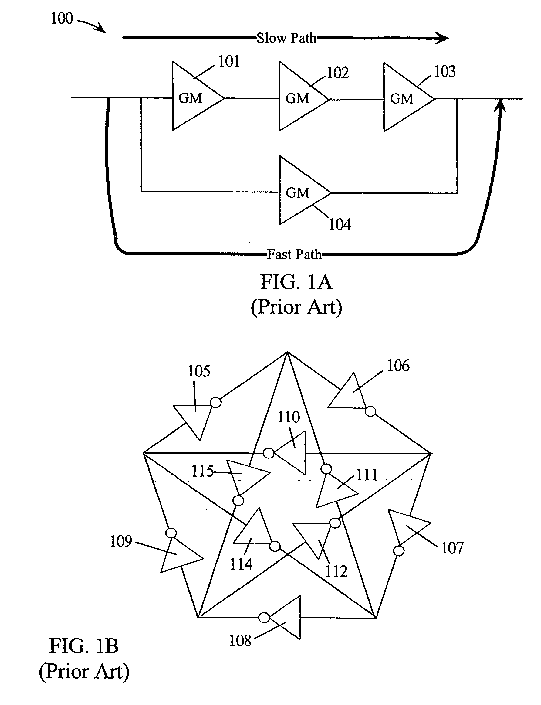
[0027]FIG. 1A illustrates an inverting stage 100 comprising a fast path with inverter 104 and a slow path with inverters 101...


PUM


Abstract

An inverting circuit comprises a first inverter in a main path having a first input and a common ouput. A second inverter receives the first input and is coupled with a first voltage controlled pass gate to the common output. A third inverter couples a second input to the common output using a second voltage controlled pass gate. A fourth inverter couples the second input to the common output using the first voltage controlled pass gate. A ring oscillator is formed using a number N of the inverting circuits with each common output coupled to the first inputs forming a main ring of a ring oscillator. The second inputs are coupled to feed-forward signals from selected outputs. The resulting signals at the common outputs are an interpolation of the first and second input signals modulated by a control voltage coupled to the first and second pass gates.

Description

TECHNICAL FIELD [0001] The present invention relates in general to complementary metal oxide semiconductor (CMOS) circuits for implementing a very high frequency voltage controlled oscillator (VCO). BACKGROUND INFORMATION [0002] Phase-locked loops (PLLs) have been widely used in high-speed communication systems because PLLs efficiently perform clock recovery or clock generation at a relatively low cost. Dynamic voltage and frequency scaling is a critical capability in reducing power consumption of power sensitive devices. Scaling, in this sense, means the ability to select high performance with nominal power supply voltages and high frequency clock operation or low performance by reducing the power supply voltage and corresponding the clock frequency. Reducing the system power is usually done when performance is not needed or when running from a limited energy source such as a battery. To allow low power operation, the PLL and other circuits must support very aggressive power / energy...

Claims


Application Information

Patent Timeline
IPC IPC(8): H03K3/03
CPCH03K3/0315H03K3/012
Inventor DRAKE, ALAN J.GEBARA, FADI H.SCHAUB, JEREMY D.
Owner GOOGLE LLC
Why Eureka
Try Eureka