
Variator for an infinitely variable toroidal drive of a motor vehicle

Inactive Publication Date: 2007-01-18
DAIMLER AG
View PDF11 Cites 3 Cited by
  • Summary
  • Abstract
  • Description
  • Claims
  • Application Information

AI Technical Summary

Benefits of technology

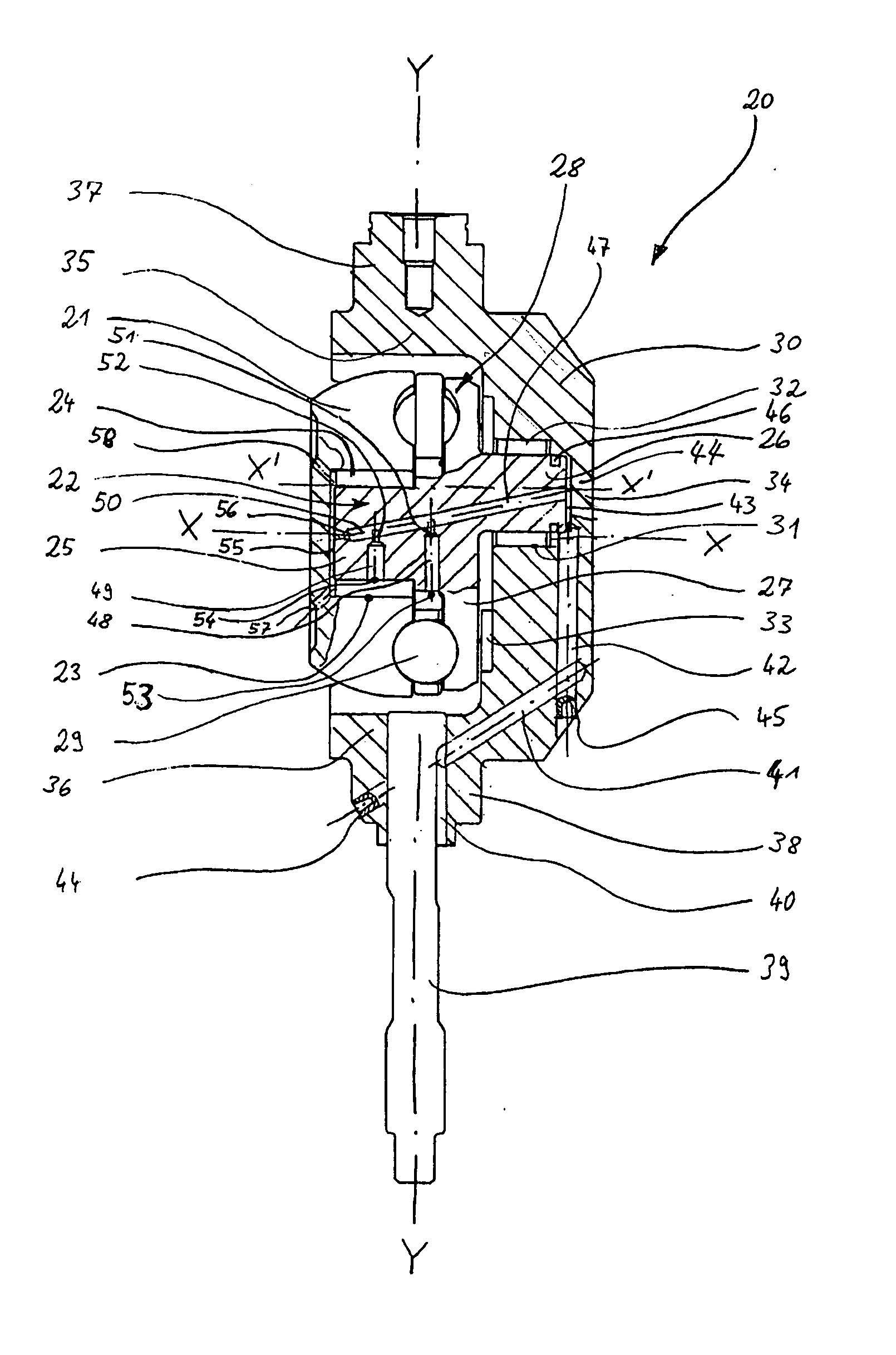
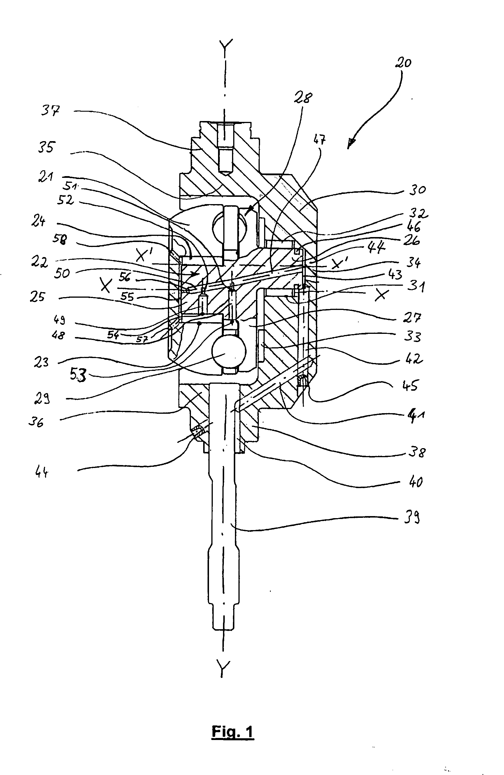
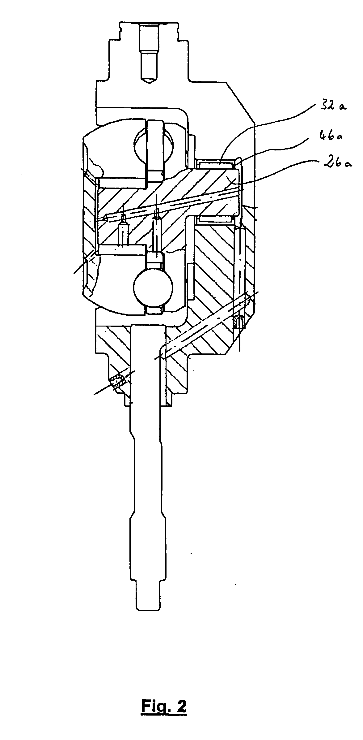
[0014] According to the invention, the lubricant line has a throttle in the region surrounding the lubricant point. The throttle is therefore not arranged in the region of a lubricant feed-in opening, for example of the support trunnion, for feeding by an adjacent component, but rather is arranged spaced apart from the feed-in opening in the direction of the flow of lubricant. This has the result that as far as the throttle, under some circumstances over longer conveying distances, an unthrottled conveying of the lubricant is possible under simple and defined conditions.
[0031] The support trunnion preferably has at least one (additional) lubricant line, the opening of which is oriented in the direction of the running surface of the roller and / or the running surface of the toroidal disk. In this way, the lubrication and / or cooling of the contact surface between toroidal disk and roller can be improved. The abovementioned lubricant line preferably has a throttle in the support trunnion for supplying the running surface of the toroidal disks or of the roller, as a result of which a specific setting of the lubricant ratios is also possible for this lubricant line. A particularly simple construction arises if lubricant lines for supplying a lubrication point in the region of a bearing and lubricant lines for lubricating the contact surface between toroidal disks and roller are supplied via a common main lubricant line.

Problems solved by technology

However, an exact optimum setting of the volume of lubricant and the pressure of the lubricant is not possible, so that an undefined distribution of lubricant to one or more lubrication points occurs.
In particular, an unnecessarily high amount of lubricant may be delivered in the region of an axial needle bearing which serves to support an eccentric shaft with respect to the support trunnion in the direction of the axis of rotation of the roller.
Problems arise with regard to the tightness, in particular if the components involved sag or deform elastically as a consequence of the mechanical stresses to which they are subjected.

Method used


Image

  • Variator for an infinitely variable toroidal drive of a motor vehicle
  • Variator for an infinitely variable toroidal drive of a motor vehicle
  • Variator for an infinitely variable toroidal drive of a motor vehicle

Examples


Embodiment Construction

[0039] The invention is used for variators of toroidal drives, particularly for motor vehicles. In this case, the toroidal transmission component can be in the form of a semi-toroid or a full-toroid. With regard to the basic design of a toroidal drive of this type, reference is made, merely by way of example, to the publications DE 102 18 356 A1, DE 101 54 928 A1 and DE 101 21 042 C1.

[0040] As schematically shown in FIG. 6, an infinitely variable toroidal drive comprises two toroidal disc D1 and D2, which, for the transmission of motion therebetween, are biased toward each other, for example, by a spring S and into engagement with at least one roller R disposed therebetween. The roller R is pivotally supported by a variator V by which its pivot position can be controlled in order to adjust the transmission ratio between the two toroidal discs D1 and D2, which depends on the radius of the circles of contact C at which the roller R is engaged by the toroidal disc D1, D2. The roller R...


PUM


Abstract

In a variator for an infinitely variable toroidal drive including a support trunnion rotatably supporting motion transmitting traction rollers and means for the lubrication and cooling of the components of the variator, in particular of the bearings, throttles are provided in the lubricant lines directly adjacent to the bearings whereby the pressure level for lubricant is raised for an improved control of the flow of the lubricant to the different lubricating points.

Description

[0001] This is a Continuation-In-Part Application of International Patent Application PCT / EP2005 / 000196 filed Jan. 12, 2005 and claiming the priority of German Patent application 10 2004 009 409.8 filed Feb. 24, 2004.BACKGROUND OF THE INVENTION [0002] The invention relates to a variator for an infinitely variable toroidal drive or transmission particularly of a motor vehicle including a support trunnion, a roller rotatably supported on the support trunnion and lubricant supply means for lubricating the various variator components [0003] In the variators for infinitely variable toroidal transmissions, particular attention is given to lubricating and / or cooling the mechanically stressed components. These components are, in particular, bearings (radial or axial bearings) which are indirectly or directly connected between a support trunnion, an eccentric shaft and / or a roller. There is a further need for lubrication and / or cooling in the region of the traction force-transmitting contact...

Claims


Application Information

Patent Timeline
IPC IPC(8): F16H15/38F16H57/04
CPCF16H15/38F16H57/049F16H57/043
Inventor ELSER, WOLFGANGHENZLER, STEFFEN
Owner DAIMLER AG
Learn More