Building material having adaptive vapor retarder
- Summary
- Abstract
- Description
- Claims
- Application Information
AI Technical Summary
Benefits of technology
Problems solved by technology
Method used
Image
Examples
example 1
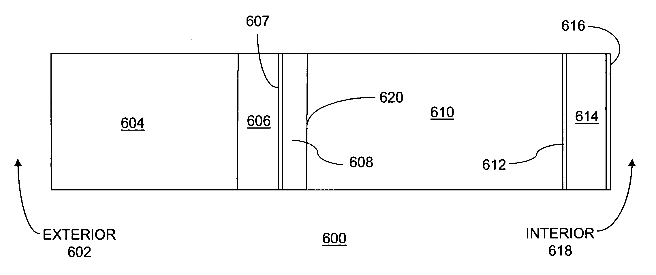
[0108]FIG. 4 shows a first configuration of a brick facade building wall structure 600, including the exterior ambient environment 602, brick 604, an air space 606, building paper 607 a 0.625 inch Oriented Strand Board (OSB) sheathing 608, a 3½″ thick fiber glass insulation batt 610 in a cavity, a vapor retarder layer 612, dry wall 614, latex paint 616, and the interior environment 618. Although the exemplary configuration is shown with a very short height, the exemplary structure can extend from the bottom to the top of an exterior wall. The adhesive laminating the vapor retarder layer 612 to the blanket or batt 610 is not shown in FIG. 4, but is understood to be present.
[0109] The transient heat and moisture simulation program employed was WUFI 3.3Pro., 2000, by Hartwig Kunzel, Achilles Karagiozis, and Andreas Holm. The WUFI ORNL / IBP model is a transient heat and mass transfer model that can be used to assess the heat and moisture distributions for a wide range of building materi...
example 2
[0112]FIG. 6 shows another exemplary configuration including, from left to right, an exterior ambient environment 802, a stucco finish 804, a “TYVEK®” spun bonded polyolefin air barrier house wrap 806 (sold by DuPont Corporation of Wilmington, Del.), an exterior sheathing 808, a 3½″ thick fiber glass batt 810, an adaptive vapor retarder film 812, an interior gypsum wallboard 814, an interior coating such as latex paint 816, and the building interior environment 818. A moisture Monitor Position 820 is at the interface of the sheathing 808 and the fiberglass batt 810. These constructions are typical for low-rise commercial projects. Although the exemplary configuration is shown with a very short height, the exemplary structure can extend from the bottom to the top of an exterior wall. The adhesive laminating the vapor retarder layer 812 to the blanket or batt 810 is not shown in FIG. 6, but is understood to be present.
[0113] Simulations were run using the structure of FIG. 6. FIGS. 7...
example 3
[0116]FIG. 9 shows simulation results for a configuration as shown in FIG. 4, wherein the smart vapor retarder 612 is an EVOH / PVOH / coextruded or laminated adaptive vapor retarder film (as described in table 35) with calculated 0.03 US Perm at 25% mean RH, 28 US Perms at 75% mean RH, 40 US Perms at 90% mean RH (as described in Table 35). The permeance of the EVOH / PVOH film (table 35) at 90% RH were estimated using the 25% and 75% mean RH perm calculations and the shape of the water vapor transmission versus % RH curve at 25° C. curve for Eval EVOH EF-F-15 with 32 mole % ethylene in the publication entitled “Permeation of Oxygen and Water Through EVOH Films as Influenced by Relative Humidity” by Zhonbin Zhang, Ian J. Britt, and Marvin A. Tung, in the Journal of Applied Polymer Science, Vol. 82, 2001, pages 1866-1872. The exterior environment evaluated was a south facing wall in Minneapolis, Minn. In the simulation of FIG. 9, the interior relative humidity had a cyclic high of 60%. The...
PUM
| Property | Measurement | Unit |
|---|---|---|
| Fraction | aaaaa | aaaaa |
| Fraction | aaaaa | aaaaa |
| Length | aaaaa | aaaaa |
Abstract
Description
Claims
Application Information
 - R&D
- Intellectual Property
- Life Sciences
- Materials
- Tech Scout
- Unparalleled Data Quality
- Higher Quality Content
- 60% Fewer Hallucinations
Browse by: Latest US Patents, China's latest patents, Technical Efficacy Thesaurus, Application Domain, Technology Topic, Popular Technical Reports.
© 2025 PatSnap. All rights reserved.Legal|Privacy policy|Modern Slavery Act Transparency Statement|Sitemap|About US| Contact US: help@patsnap.com


