Line narrowed laser apparatus

a laser apparatus and narrowing technology, applied in laser details, excitation process/apparatus, active medium materials, etc., can solve the problems of deteriorating quality of integrated circuits, affecting the efficiency of laser equipment,

Active Publication Date: 2007-01-18
USHIO DENKI KK +1
View PDF7 Cites 22 Cited by
  • Summary
  • Abstract
  • Description
  • Claims
  • Application Information

AI Technical Summary

Benefits of technology

[0069]FIG. 22 is a diagram illustrating a flowchart of beam correction control;
[0070]FIG. 23 is a diagram illustrating a flowchart of beam correction control;

Problems solved by technology

However, since the natural oscillation widths of the KrF and ArF excimer lasers are wide at approximately 350 to 400 pm, chromatic aberration occurs if these projection lenses are used, so that the resolution declines.
However, in recent years it has come to be said that there are cases where the quality of the integrated circuits can deteriorate even if this spectral purity width is substantially narrower than the width designed for an optical system.
However, with the conventional technique described in the aforementioned JP-A-2001-267673, in conjunction with the control of the spectral purity width, the central wavelength also changes concomitantly.
For this reason, it is difficult to independently perform the central wavelength control for allowing the central wavelength to agree with a desired value and the spectral line width control for keeping the spectral purity width within a predetermined allowable range.
(1) In the control of the central wavelength, it is desirable to perform feedback control for each pulse, but this involves complex control.
However, in a case where there is a need to dynamically control the wavelength such as when an instruction on the change of a target wavelength is given from an exposure device, there is a possibility of affecting the accuracy of the central wavelength control.
Furthermore, with the conventional technique described in JP-A-2000-312048, if an attempt is made to control the spectral line width to a target spectral purity width E95 by controlling the grating bending; the following problems occur.
Moreover, in cases where the range of ±0.1 pm has been exceeded due to the effect of such as a thermal load and acoustic waves, the stabilization of the spectral purity width E95 is difficult.
Therefore, the grating bending mechanism is not suitable for fast control of the spectral purity width E95.
As described above, there are various problems in performing the control of the spectral purity width E95 by the waveform shifting and grating bending, and it has been difficult to effect the control of the spectral purity width E95 in a wide control range while imparting practically no effect to the control of the central wavelength.

Method used


Image

  • Line narrowed laser apparatus
  • Line narrowed laser apparatus
  • Line narrowed laser apparatus

Examples


first embodiment

[First Embodiment]

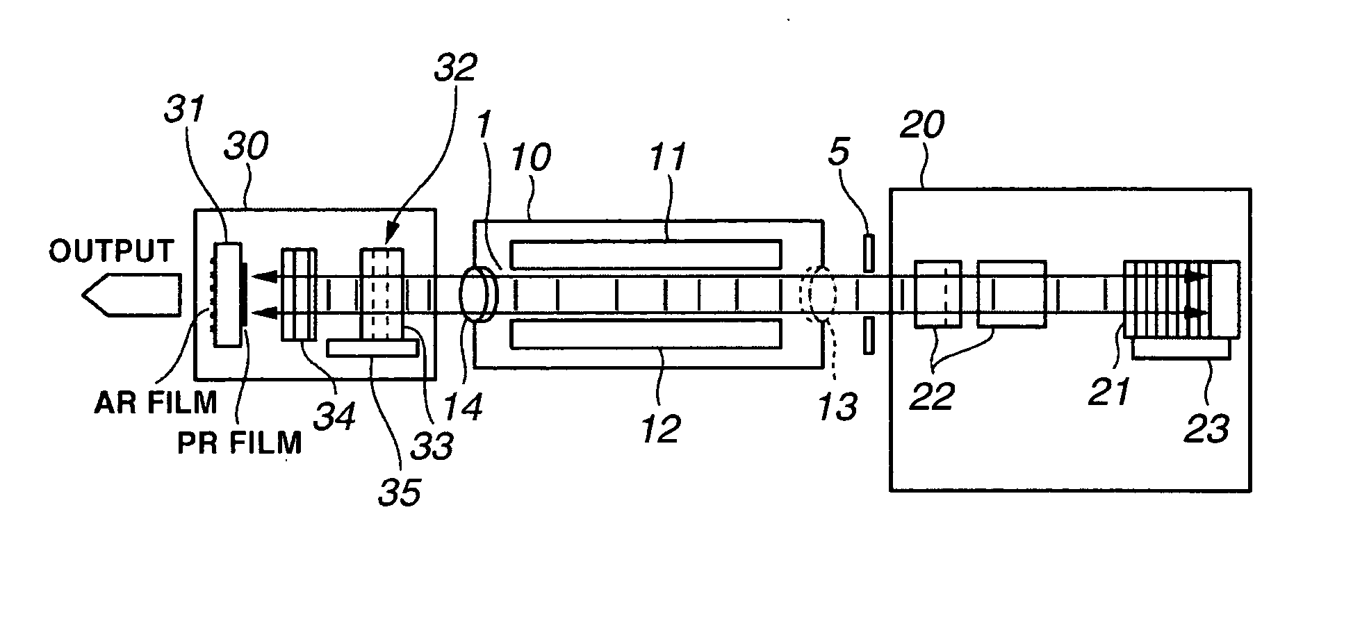
[0075]FIG. 1A is a top view of the configuration of a line narrowed laser apparatus in accordance with a first embodiment. FIG. 1B is a side elevational view of the configuration of the line narrowed laser apparatus having a wavefront corrector.

[0076] As shown in FIGS. 1A and 1B, an ordinary line narrowing module 20 is disposed on the rear side (right side in the drawing) of a laser chamber 10, and a wavefront adjusting module 30 is disposed on the front side (left side in the drawing) thereof.

[0077] A pair of discharge electrodes 11 and 12, which are spaced apart a predetermined distance, whose longitudinal directions are parallel, and whose discharge surfaces are opposed to each other, are provided inside the laser chamber 10. Further, windows 13 and 14 are provided at a laser light outputting portion on the optical axis of the laser light in the laser chamber 10. The windows 13 and 14 are formed of a material which is permeable to the laser light, such as CaF2...

second embodiment

[Second Embodiment]

[0111] In this embodiment, a description will be given of a form different from the first embodiment.

[0112]FIG. 6 is a side elevational view of the configuration of the line narrowed laser apparatus in accordance with a second embodiment. The difference between the first embodiment and the second embodiment lies in the internal configuration of the wavefront adjusting module.

[0113] As shown in FIG. 6, the wavefront adjusting module 30 has the wavefront corrector 32. The wavefront corrector 32 has a cylindrical convex lens 37, a cylindrical concave lens 36, and the linear stage 35 for holding the concave lens 36. The convex lens 37 has one surface processed into a flat shape and the other surface processed into a cylindrical shape. Meanwhile, the concave lens 36 has one surface processed into a flat shape and the other surface processed into a cylindrical shape. The convex lens 37 and the concave lens 36 are arranged on the optical axis such that the cylindrical ...

third embodiment

[Third Embodiment]

[0126] In this embodiment, a description will be given of still another form different from the first embodiment.

[0127]FIG. 7 is a side elevational view of the configuration of the line narrowed laser apparatus in accordance with a third embodiment. FIG. 8 shows a cross section taken along line A—A in FIG. 7. The difference between the first embodiment and the third embodiment lies in the configuration of the front side of the laser.

[0128] As shown in FIG. 7, a deformable mirror 70, which is an end mirror, is disposed on the front side of the laser chamber 10. In this embodiment, the laser wavefront is varied (modified) by shaping the configuration of the total reflection surface of the deformable mirror 70.

[0129] The laser resonator is formed by the grating 21 Littrow-configured on the rear side of the laser chamber 10 and the deformable mirror 70 disposed on the front side. A 45-degree incident beam splitter 71 is disposed on the optical path between the laser...


PUM


Abstract

The control of the spectral purity width E95 is performed while imparting practically no effect to the control of a central wavelength, and the spectral purity width E95 is stabilized. A wavefront adjuster 32 is provided on an output side of the interior of an optical resonator, i.e., on an output coupler 31 side. Light generated in a laser chamber 10 is transmitted through the wavefront adjuster 32 from the laser chamber 10 side, and reaches the output coupler 31. In the wavefront adjuster 32, the distance between concave and convex lenses 33 and 34 is adjusted so that a desired spectral purity width E95 can be obtained. Then, when the light passes through the wavefront adjuster 32, the wavefront of the light is adjusted to a desired wavefront.

Description

BACKGROUND OF THE INVENTION [0001] 1. Field of the Invention [0002] The present invention relates to a line narrowed laser apparatus, and more particularly to a line narrowed excimer laser apparatus or a line narrowed F2 laser apparatus serving as a light source of a reduction projection exposure device used for the manufacture of a semiconductor, wherein a spectral index value such as the spectral purity width of the laser light is controlled. [0003] 2. Related Art [0004] Hereafter, a description will be given of respective items of conventional techniques of the line narrowed laser apparatus used as a light source of a reduction projection exposure device. (Light Source for Exposure) [0005] In conjunction with trends toward finer patterning and higher integration of semiconductor integrated circuits, there has been a demand for improvement of resolution in semiconductor exposure devices. For this reason, attempts are underway to shorten the wavelength of light emitted from a ligh...

Claims


Application Information

Patent Timeline
Patent Type & Authority Applications(United States)
IPC IPC(8): H01S3/22H01S3/097H01S3/08H01S3/223
CPCH01S3/08009H01S3/08031H01S3/0971H01S3/1055H01S3/225H01S3/2258H01S3/2308H01S3/137
Inventor WAKABAYASHI, OSAMUKUMAZAKI, TAKAHITO
Owner USHIO DENKI KK
Why Eureka
Try Eureka