
Thin film transistor array panel and fabrication

Active Publication Date: 2007-01-18
SAMSUNG DISPLAY CO LTD
View PDF2 Cites 2 Cited by
  • Summary
  • Abstract
  • Description
  • Claims
  • Application Information

AI Technical Summary

Benefits of technology

[0005] In accordance with the invention, the after image problem is eliminated even though the metal patterns for the multi-layered data lines structured of an Al film and an underlying Mo film and the intrinsic semiconductor are etched using the same photoresist pattern. The diffusion of Mo into the semiconductors and the splitting of impurities from the lower Al film are prevented from polluting the semiconductor channel during wet etching. In forming the channel areas, the flow ratio of the chlorine-containing gas and the fluorine-containing gas is controlled within a predetermined ratio.

Problems solved by technology

The various patterning steps such as applying the photolithographic mask, exposing to light, developing, and cleansing are repeated for each separate mask thereby making the manufacturing process costly and time consuming.
However, when the metal layer for the data lines and the semiconductor are etched using the same mask, some of the semiconductor layer is left on the entire surface under the etched metal layer causing afterimages because of light leakage from the semiconductor area.

Method used


Image

  • Thin film transistor array panel and fabrication
  • Thin film transistor array panel and fabrication
  • Thin film transistor array panel and fabrication

Examples


Embodiment Construction

[0015] An exemplary embodiment of the present invention will hereinafter be described in detail with reference to the accompanying drawings. As those skilled in the art would realize, the described embodiments may be modified in various different ways, all without departing from the spirit or scope of the present invention. In the drawings, the thickness of layers, films, panels, regions, etc., are exaggerated for clarity. Like reference numerals designate like elements throughout the specification. It will be understood that when an element such as a layer, region, or substrate is referred to as being “on” another element, it can be directly on the other element or intervening elements may also be present. In contrast, when an element is referred to as being “directly on” another element, there are no intervening elements present.

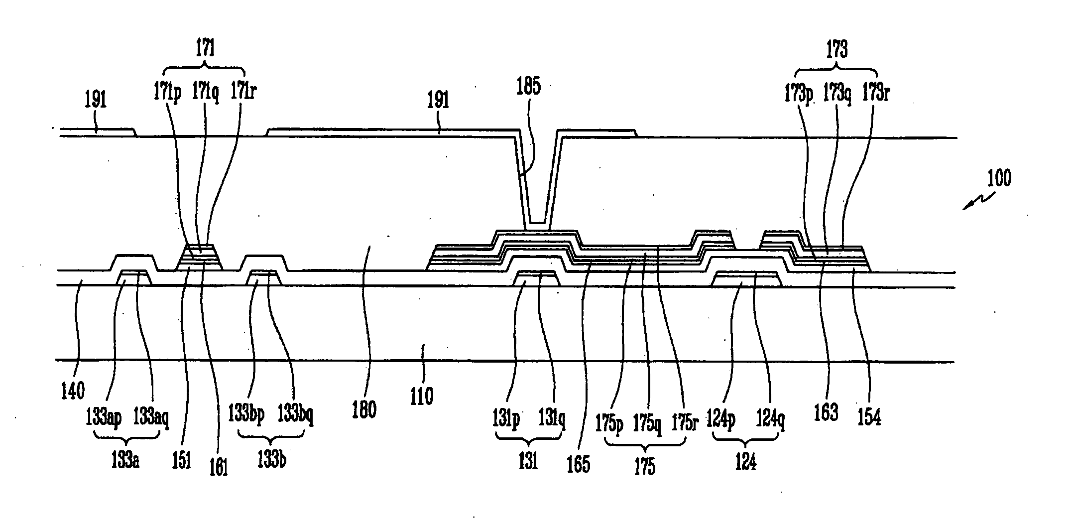
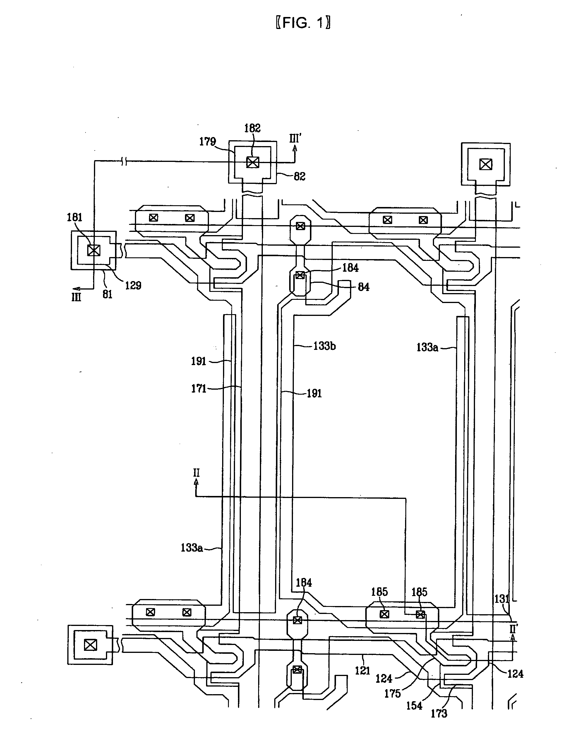
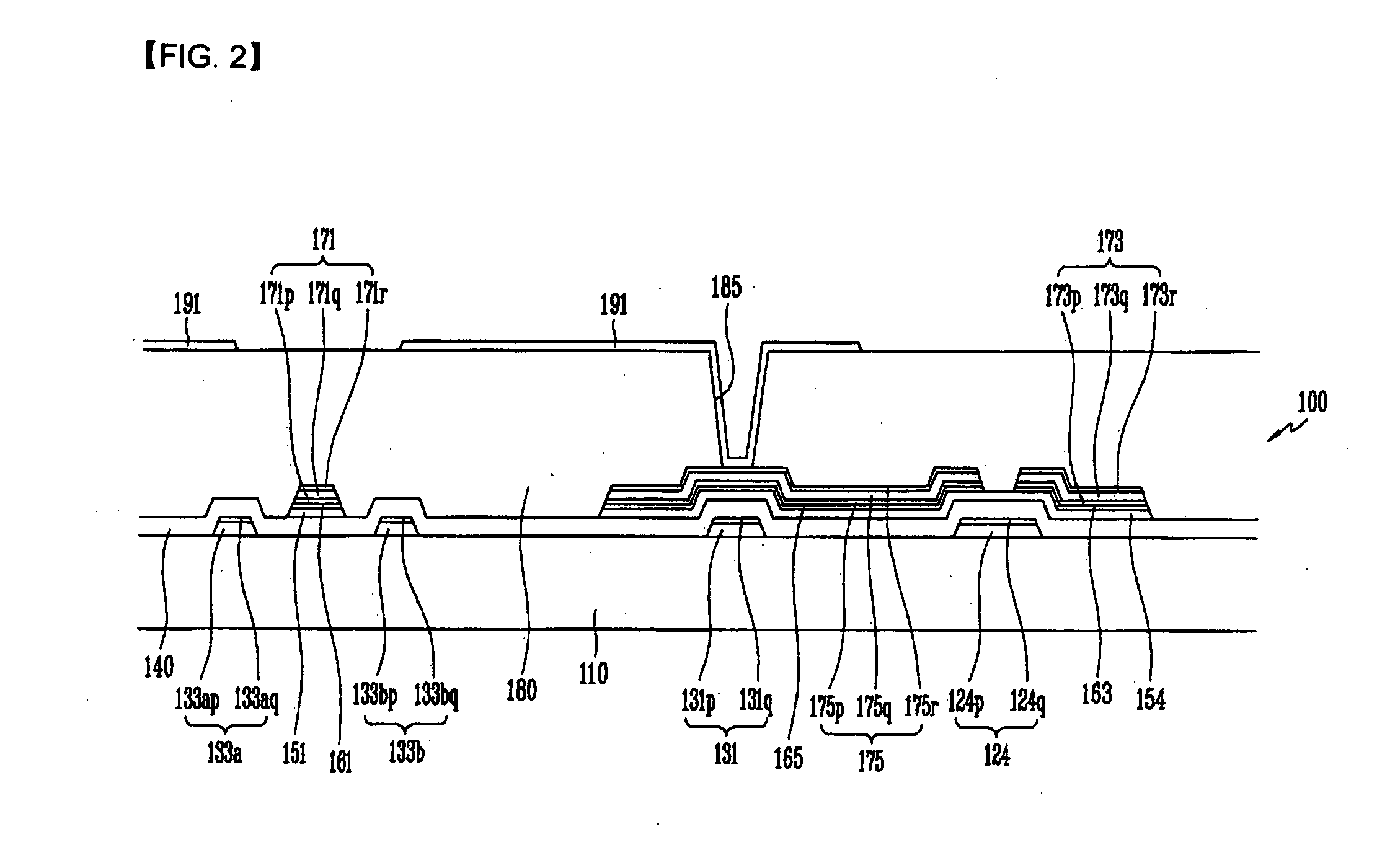
[0016] A TFT array panel according to an embodiment of the present invention will be described in detail with reference to FIGS. 1 to 3. FIG. 1 is layout...


PUM


Abstract

The present invention provides a manufacturing method of a thin film transistor array panel, which includes forming a gate line on a substrate; forming a gate insulating layer, a semiconductor layer, and an ohmic contact on the gate line; forming a first conducting film including Mo, a second conducting film including Al, and a third conducting film including Mo on the ohmic contact; forming a first photoresist pattern on the third conducting film; etching the first, second, and third conducting films, the ohmic contact, and the semiconductor layer using the first photoresist pattern as a mask; removing the first photoresist pattern by a predetermined thickness to form a second photoresist pattern; etching the first, second, and third conducting films using the second photoresist pattern as a mask to expose a portion of the ohmic contact; and etching the exposed ohmic contact using a Cl-containing gas and a F-containing gas.

Description

CROSS-REFERENCE TO RELATED APPLICATION [0001] This application claims priority to and the benefit of Korean Patent Application No. 10-2005-0062730 filed in the Korean Intellectual Property Office on Jul. 12, 2005, the contents of which is hereby incorporated by reference. FIELD OF THE INVENTION [0002] The present invention relates to a thin film transistor array panel and a manufacturing method thereof. DESCRIPTION OF THE RELATED ART [0003] Liquid crystal displays (LCDs) are one of the most widely used flat panel displays. An LCD includes a liquid crystal (LC) layer interposed between two panels wherein one panel (referred to as “a thin film transistor array panel”) has a plurality of pixel electrodes in a matrix and the other (referred to as “a common electrode panel”), has a common electrode covering the entire surface of the panel. The LCD displays images by applying voltages to the field-generating electrodes to generate an electric field in the LC layer that determines the orie...

Claims


Application Information

Patent Timeline
IPC IPC(8): H01L31/113
CPCG02F2001/13629H01L27/124H01L29/458G02F1/13629G02F1/136286H01L27/12H01L27/1214H01L29/78696
Inventor KIM, SANG-GABLEE, WOO-GEUNKIM, SHI-YULJU, JIN-HOKIM, JANG-SOOWHANGBO, SANG-WOOOH, MIN-SEOKRYU, HYE-YOUNGCHIN, HONG-KEE
Owner SAMSUNG DISPLAY CO LTD
Learn More