
Electrochromic devices utilizing very low band gap conjugated counter electrodes: preparation and use

Active Publication Date: 2007-01-11
UNIV OF CONNECTICUT
View PDF14 Cites 68 Cited by
  • Summary
  • Abstract
  • Description
  • Claims
  • Application Information

AI Technical Summary

Benefits of technology

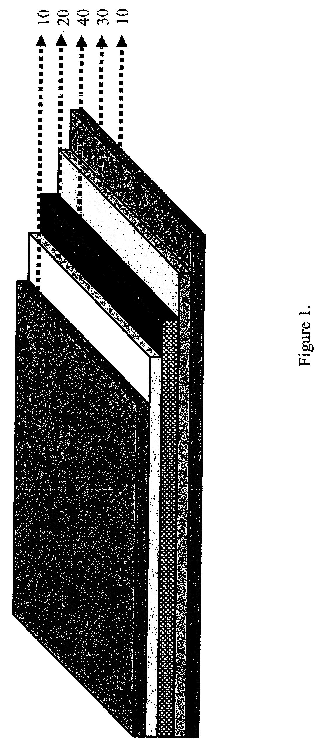
[0006] Disclosed herein is an electrochromic device comprising a first layer comprising a first conjugated polymer, wherein the first conjugated polymer has a band gap of less than or equal to about 1.5 eV and an Lmax absorption peak of greater than or equal to about 750 nm in the neutral, oxidized, and reduced forms, and wherein the first layer functions as an ion-storage layer; a second layer comprising a second conjugated polymer, wherein the second conjugated polymer has a band gap of less than about 2.5 eV and wherein the second layer functions as an electrochromic in the visible region of the electromagnetic spectrum; an electrolyte layer disposed between and in contact with the first layer and the second layer; a first electrode in electrical communication with the first layer; and a second electrode in electrical communication with the second layer.
[0007] In another embodiment, an electrochromic device comprises a first layer comprising a first conjugated polymer, wherein the first conjugated polymer has a band gap of less than or equal to about 1.5 eV and a Lmax absorption peak of greater than or equal to about 750 nm in the neutral, oxidized, and reduced forms, and wherein the first layer functions as an ion-storage layer; a second layer comprising an ion-chelating inorganic structure that reversibly binds to counter-ions; an electrolyte layer in cont

Problems solved by technology

A drawback of liquid crystals is that most require a constant supply of power to generate the effect.
Solution phase electrochromics and liquid crystal configurations are limited by the diffusion speed of the electrochromic materials and supporting electrolytes towards the electrode.

Method used


Image

  • Electrochromic devices utilizing very low band gap conjugated counter electrodes: preparation and use
  • Electrochromic devices utilizing very low band gap conjugated counter electrodes: preparation and use
  • Electrochromic devices utilizing very low band gap conjugated counter electrodes: preparation and use

Examples


examples

[0078] Poly(thieno[3,4-b]thiophene) and poly(dibenzylProDOT) were electrochemically deposited at a potential of 1.3 V (versus non-aqueous Ag / Ag+, calibrated to be 0.45 V versus NHE) onto one-side of ITO coated glass. The oxidized poly(thieno[3,4-b]thiophene) coated on the ITO-glass was switched to the neutral form in 0.1 M lithium triflate solution by applying −0.8 V (versus non-aqueous Ag / Ag+). The gel-electrolyte composed of 7.0 grams (g) poly(ethyleneglycolethylether methacrylate), 1.0 g lithium trifluoromethanesulfonate, 3.0 g propylene carbonate and 17.5 milligrams (mg) 2,2-dimethoxy-2-acetophenone was sandwiched between the neutral (thieno[3,4-b]thiophene) and the oxidized poly(dibenzylProDOT) and cured for 20 min using a 365 nm UV lamp. 50-100 mm glass beads dispersed in the gel electrolyte composition acted as the spacer to keep the two electrodes apart. The sides of the solid-state device was then sealed using a polyurethane-acrylate to prevent moisture from entering the de...


PUM


Abstract

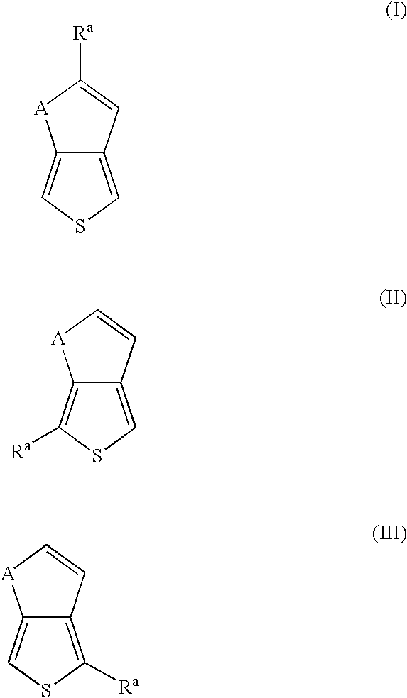
Disclosed herein are electrochromic devices using a very low band-gap conjugated polymer having a band gap (Eg) of less than or equal to about 1.5 eV, and having little or no electrochromism in the visible region of the electromagnetic spectrum.

Description

CROSS-REFERENCE TO RELATED APPLICATIONS [0001] This application claims the benefit of U.S. Patent Application Ser. No. 60 / 698,049, filed Jul. 11, 2005, which is incorporated by reference herein in its entirety.BACKGROUND [0002] Electrochromic devices take advantage of materials that are able to change their optical properties in a reversible and repeatable way under the application of an electrical current or potential. These materials include inorganic semiconductors and certain conjugated polymers. [0003] These devices have the advantage of being able to tune through various redox states by the application of a small voltage to the devices as opposed to the dependence of external lighting conditions by photochromic materials. Known configurations of electrochromic devices include solution phase electrochromics where the diffusion of the electrochromic species from the solution to the electrode is followed by a redox reaction on the electrode surface accompanied by a color transiti...

Claims


Application Information

Patent Timeline
IPC IPC(8): G02F1/15G02F1/1503
CPCC09K9/02G02F1/1521C09K2211/1441G02F1/1503
Inventor SOTZING, GREGORY A.SESHADRI, VENKATARAMANAN
Owner UNIV OF CONNECTICUT
Learn More