
Device and method for mixing liquids and oils or particulate solids and mixtures generated therefrom

a technology of liquid and oil, which is applied in the direction of mixing, transportation and packaging, chemical instruments and processes, etc., can solve the problems of increasing heat and breaking the bonds holding large fluid arrays together, mixing liquids, and generating additional cavitational energy, so as to achieve sufficient acoustic energy and increase heat

Inactive Publication Date: 2007-01-04
AQUAPHOTONICS INC
View PDF23 Cites 63 Cited by
  • Summary
  • Abstract
  • Description
  • Claims
  • Application Information

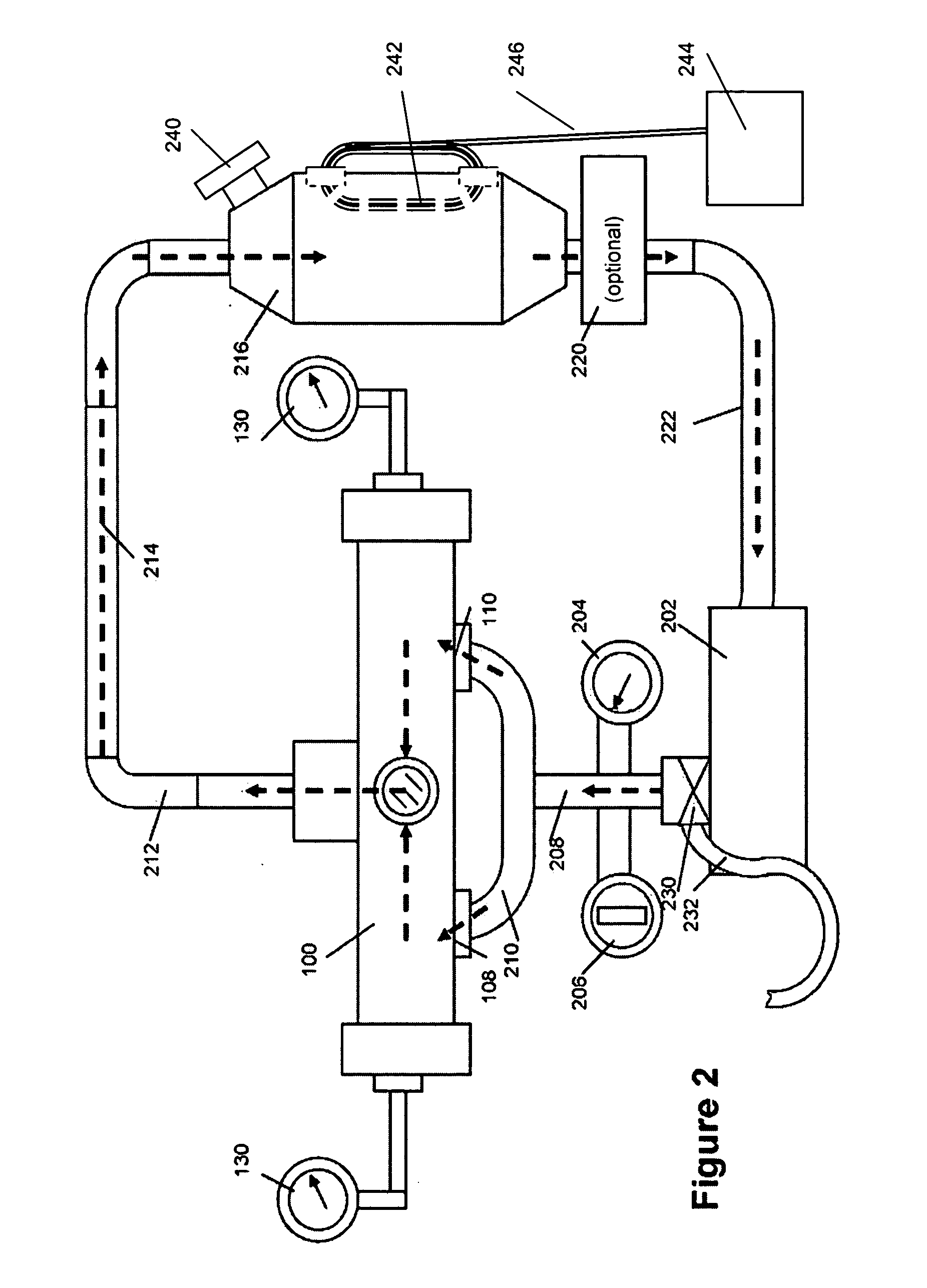
AI Technical Summary

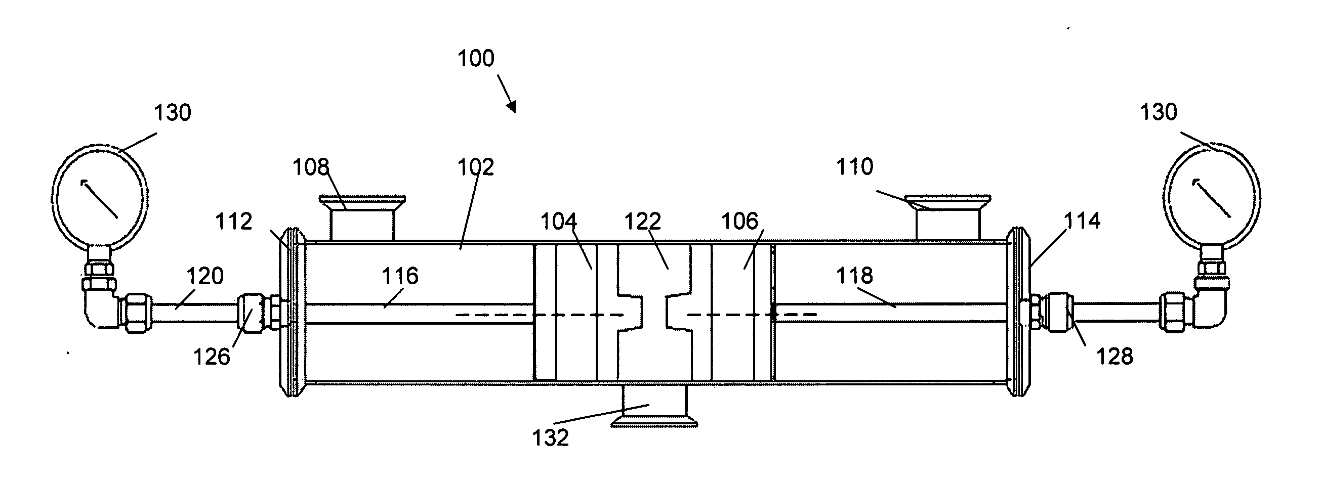
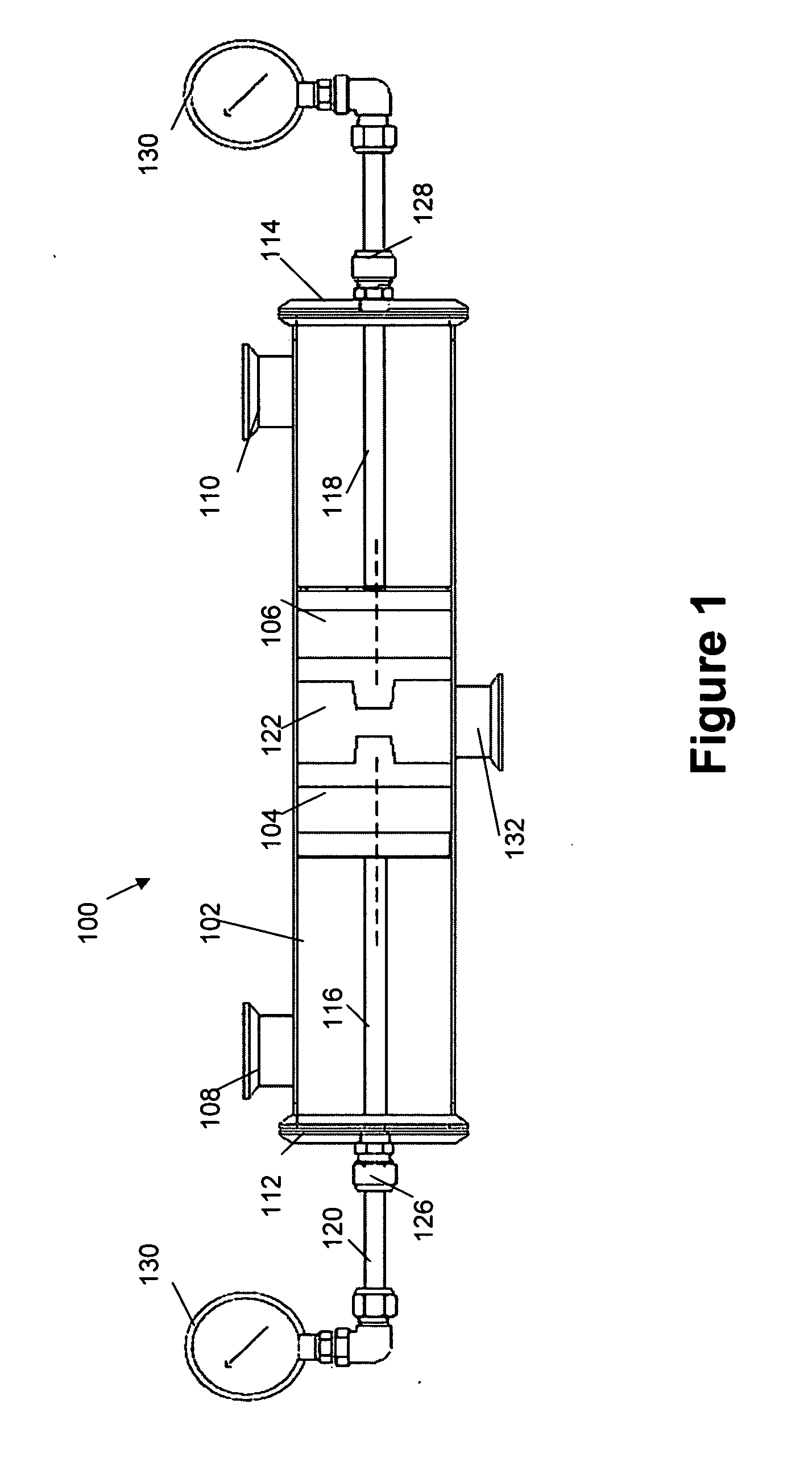
Benefits of technology

[0009] It is an advantage of the present invention to provide a device and method for processing liquids to dissolve components in water that are traditionally considered to be insoluble.
[0010] It is another advantage of the present invention to provide compositions of water and dissolved components created using the inventive device and method for cosmetic and therapeutic applications and for use in foods and manufacturing industries.
[0011] According to the present invention, by subjecting a mixture of the material(s) to be dissolved and water to a vortexing assembly such as that disclosed in U.S. Pat. No. 6,521,248, a true solution or stable suspension of the material can be formed. The vortexing assembly pressurizes a starting fluid to a first pressure followed by rapid depressurization to a second pressure to create a partial vacuum pressure that results in the formation of cavitation bubbles that subsequently implode when they encounter a higher pressure. The thermo-physical reactions provided by the implosion of the cavitation bubbles result in an increase in heat and breaking of bonds holding large fluid arrays together. This process can be repeated until a desired physical-chemical trait of the fluid mixture is obtained.
[0012] In the preferred embodiment a plurality of rotational vortices, also referred to as nozzles, are used. The nozzles are enclosed within a housing includes an inlet corresponding to each nozzle and an outlet for discharging the mixed fluid. The liquid is introduced through openings in the sides of the nozzles to spin the liquid through one 360 degree rotation, then discharge the liquid through an exit opening at the radial center of the nozzle. The nozzle outlets are each directed into an exit volume in an arrangement so that the output stream from each of the nozzles collides with the other outputs. This high energy collision results in generation of additional cavitational energy and mixing of the liquid. It is therefore preferred that the nozzles are axially aligned, with two outlets directly opposing each other. In the exemplary embodiment, the housing is tubular in shape so that two opposing nozzles are axially aligned with the housing. In the preferred embodiment, the separation between the nozzles is made variable by mounting the nozzles on sliding attachments to permit adjustment of the desired interaction based upon liquid viscosity or nature of the component(s) to be mixed.
[0013] In addition to the use of rotational vortices, other techniques known to those of skill in the art can be used to create cavitation in a fluid so long as the cavitating source is suitable to generate sufficient acoustic energy to break the large arrays. The acoustic energy produced by the cavitation provides energy to break the large fluid arrays into smaller fluid clusters. For example, acoustical transducers may be utilized to provide the required cavitation source. In addition, a fluid may be forced through a tube having a constriction in its length providing for a high pressure before the constriction, which is rapidly depressurized within the constriction and then pressurized again after the restriction. Another example includes forcing a fluid in reverse direction through a volumetric pump.
[0014] In a preferred embodiment of the inventive method, water that has previously been fractionated using the cavitation device is added to the device and the device is activated. The material to be mixed, e.g., oil, is added to the water in the device. The water and material are processed through the device for a specified time, which preferably involves multiple cycles through the device.

Problems solved by technology

The thermo-physical reactions provided by the implosion of the cavitation bubbles result in an increase in heat and breaking of bonds holding large fluid arrays together.
This high energy collision results in generation of additional cavitational energy and mixing of the liquid.

Method used


Image

  • Device and method for mixing liquids and oils or particulate solids and mixtures generated therefrom
  • Device and method for mixing liquids and oils or particulate solids and mixtures generated therefrom
  • Device and method for mixing liquids and oils or particulate solids and mixtures generated therefrom

Examples


example 1

[0062] A mixture of 10% by volume Olive Oil in water is subjected to the cavitation process with test samples taken at 115°, 125°, 135° and 140° C. for determination of the amount of oil dissolved in the water. The maximum amount was 0.04 grams per 10 mL of water.

[0063] The oil in water solution has a milky white appearance with a faint Olive Oil odor. The solution was applied to the hands and arms as a lotion and was absorbed very rapidly into the skin and did not leave an oily film or feeling on the skin. The solution was subjected to centrifuge at 12,000 rpm for three 20 minute periods without causing a separation. The solution was further subjected to centrifuge at 20,000 rpm for three 20 minute periods, without separation or change in the solution.

example 2

[0064] 100 g of ZnO powder, 99.99% purity was combined with 20 1 of Penta® water and processed until the temperature reached 140° F. The calculated particle size, according to the Turbiscan™ device was between 0.04 μm and 0.012 μm.

example 3

[0065] The device used to generate the oil in water according to Example 1 was further fitted on the exterior thereof with a cooling jacket or heat exchange system such that, as heat was generated, it was pulled away from the outside of the device, thereby maintaining the process temperature at a desired point. The system was allowed to process for two hours at 100° F. after which the heat exchanger was removed and the temperature of the liquid was allowed to increase to 140° F. after which the device was turned off and the processed oil in water collected. The average particle size was determined to be 115 nm.


PUM

PropertyMeasurementUnit
Temperatureaaaaaaaaaa
Viscosityaaaaaaaaaa
Distanceaaaaaaaaaa

Abstract

A cavitation device includes a pair of axially aligned opposing nozzles within a housing. Liquid is introduced into the nozzles at a pressure to create rotational vortices within the nozzles, causing cavitation. The thermo-physical reactions resulting from cavitation produce an increase in heat and breaking of the bonds holding large fluid arrays together. Additional cavitation is induced by a collision between the liquid outputs of the opposing nozzles to enhance mixing. By subjecting a mixture of material(s) to be dissolved in water to a cavitation device, a true solution of a lipophilic and water or stable suspension of particulate solids in water can be formed.

Description

CROSS-REFERENCE TO RELATED APPLICATIONS [0001] This application claims priority to each of provisional application No. 60 / 595,095, filed Jun. 6, 2005, No. 60 / 596,170, filed Sep. 6, 2005, No. 60 / 780,947, filed Mar. 8, 2006, and No. 60 / 801,231, filed May 16, 2006, and is a continuation-in-part of application Ser. No. 11 / 302,967, filed Dec. 13, 2005, which claims the priority to provisional applications No. 60 / 635,915, filed Dec. 13, 2004, No. 60 / 596,170, filed Sept. 6, 2005, No. 60 / 594,612, filed Apr. 22, 2005 and No. 60 / 594,540, filed Apr. 15, 2005, and which is a continuation-in-part of Ser. No. 10 / 420,280, filed Apr. 21, 2003; which is a continuation-in-part of application Ser. No. 10 / 301,416, filed Nov. 21, 2002, which is a continuation-in-part of application Ser. No. 09 / 698,537, filed Oct. 26, 2000, now issued as U.S. Pat. No. 6,521,248, which claims priority to provisional application No. 60 / 161,546, filed Oct. 26, 1999. Each of the above-identified applications is incorporated ...

Claims


Application Information

Patent Timeline
IPC IPC(8): A61K8/00
CPCB01F3/0807B01F5/0256B01F3/12B01F23/41B01F23/50B01F25/23
Inventor HOLLOWAY, WILLIAM D. JR.HOLLOWAY, MICHAEL A.TARBET, KENNETH H.
Owner AQUAPHOTONICS INC
Learn More