
Nanotube Transistor and Rectifying Devices

a technology of carbon nanotube and rectifying device, which is applied in the manufacture of nanostructures, semiconductor devices, electrical devices, etc., can solve the problems of pushing the boundaries of silicon materials, increasing performance requirements, etc., and achieves low yields

Inactive Publication Date: 2007-01-04
ETAMOTA CORP
View PDF38 Cites 96 Cited by
  • Summary
  • Abstract
  • Description
  • Claims
  • Application Information

AI Technical Summary

Benefits of technology

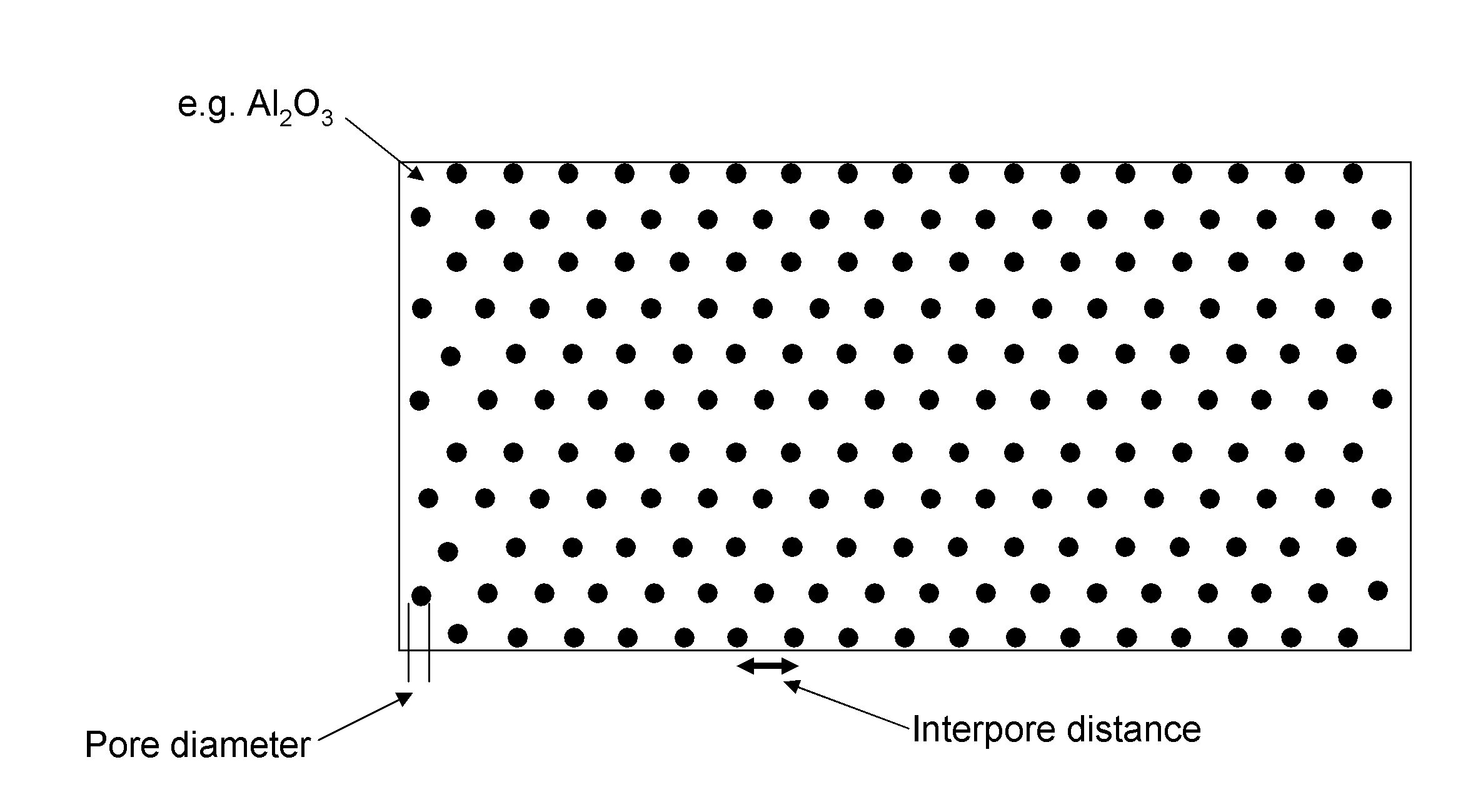
[0013] In an embodiment, the invention is a field-effect transistor device for power applications including a number of single-walled carbon nanotubes within a porous alumina template or other porous structure. The single-walled carbon nanotubes are either directly synthesized within the pores or are transferred to the pores after synthesis. Source, drain, and gate electrodes are placed so that multiple single-walled carbon nanotubes are connected in a vertical fashion. The device is capable of high current densities, high power, and efficient power delivery.
[0015] In an embodiment, the gate electrode can be etched vertically into the aluminum oxide structure or other porous structure, which would effectively electrically modulate the entire length or a portion of the length of the semiconducting single-walled carbon nanotubes and turn it on and off. The gate can alternatively be patterned on one or both sides of the aluminum oxide structure without etching. The semiconducting single-walled carbon nanotubes can be p-type or n-type based on environmental exposure, for example, to ambient, intentional doping or coatings, annealing, or the like, or based on other methods. Therefore the power transistor can be p-type, n-type, or a complementary configuration. Any unwanted or extraneous single-walled carbon nanotubes or portions of single-walled carbon nanotubes are removed by any competent method such as chemical, electrical, or mechanical methods, or the like. There are large densities of possible connections, and it is not necessary for every pore to contain a functioning semiconducting single-walled carbon nanotube device. Redundancy allows for defects, failures, and low yields.

Problems solved by technology

However, demand for increasing performance requirements is pushing the boundaries of silicon material.

Method used


Image

  • Nanotube Transistor and Rectifying Devices
  • Nanotube Transistor and Rectifying Devices
  • Nanotube Transistor and Rectifying Devices

Examples


Embodiment Construction

[0054] The invention provides a carbon nanotube transistor device and techniques for manufacturing such a transistor device. In a specific embodiment, the carbon nanotube transistor is a single-wall carbon nanotube (SWNT) transistor, where the single-walled carbon nanotube is a channel of the transistor. A specific application of the SWNT transistor of the invention is as a power transistor, a type of transistor capable of passing relatively high currents compared to standard transistors. Further, the invention provides diode, silicon-controlled rectifier, and other related devices having carbon nanotubes, and methods for making such devices. These may be manufactured independently or in combination with transistors devices of the invention.

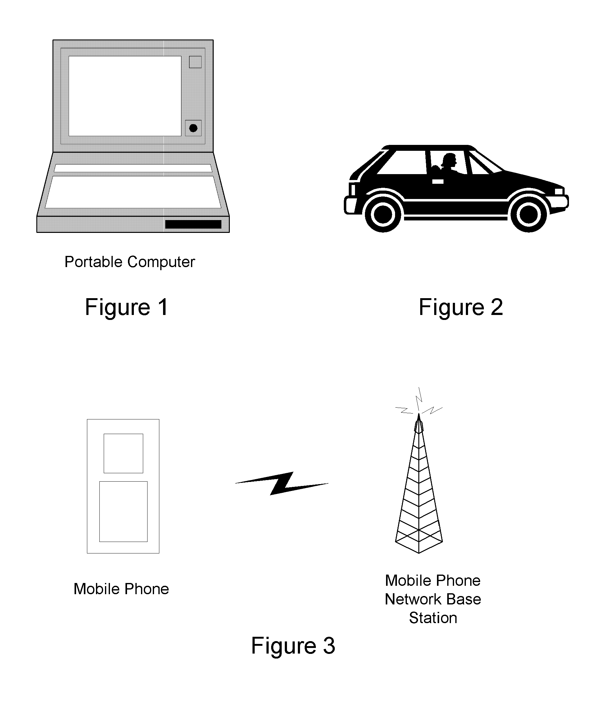
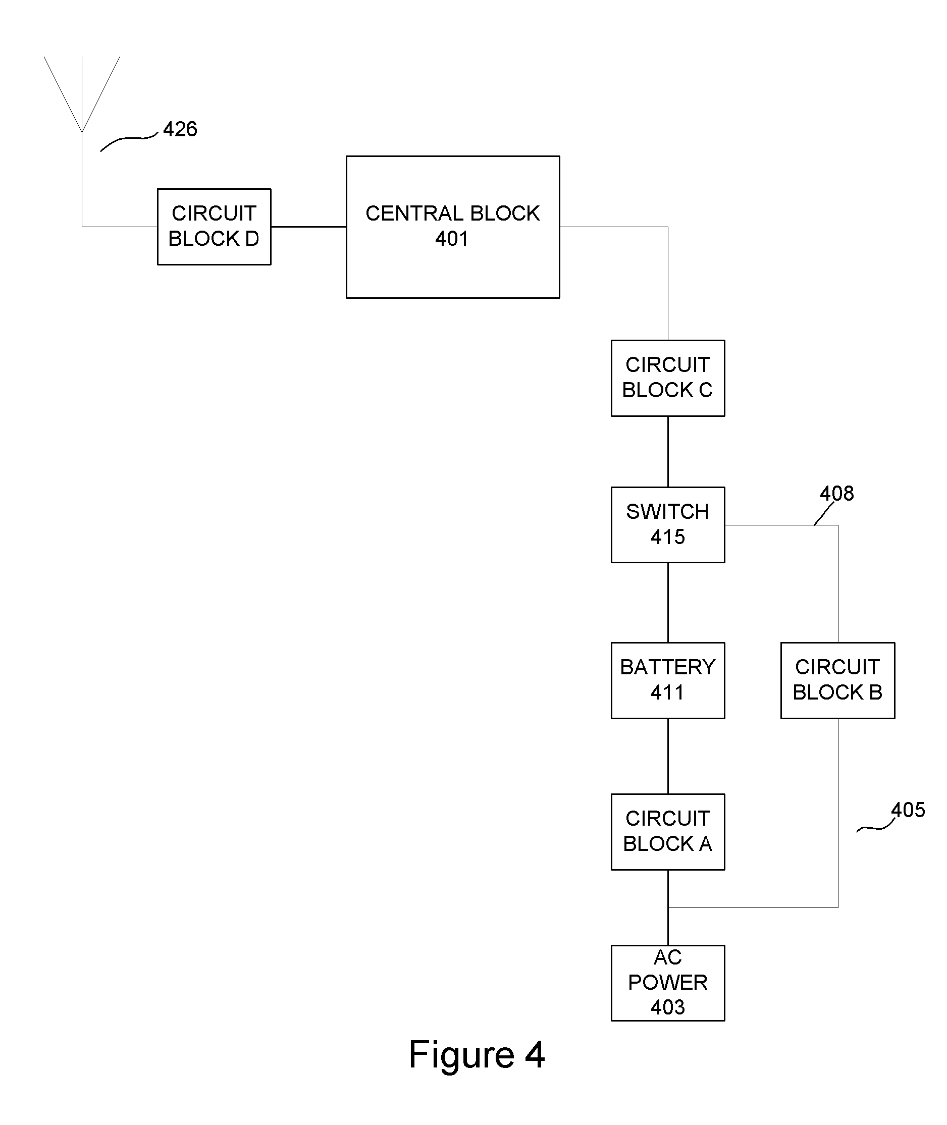
[0055]FIG. 1 shows an example of an electronic system incorporating one or more carbon nanotube transistors or rectifying devices of the invention, or combinations of these. Electronic systems come in many different configurations and sizes. Som...


PUM


Abstract

Single-walled carbon nanotube transistor and rectifying devices, and associated methods of making such devices include a porous structure for the single-walled carbon nanotubes. The porous structure may be anodized aluminum oxide or another material. Electrodes for source and drain of a transistor are provided at opposite ends of the single-walled carbon nanotube devices. A gate region may be provided one end or both ends of the porous structure. The gate electrode may be formed into the porous structure. A transistor of the invention may be especially suited for power transistor or power amplifier applications.

Description

[0001] This application claims the benefit of U.S. provisional patent applications Nos. 60 / 611,055, filed 2004 Sep. 16; 60 / 61 0,669, filed 2004 Sep. 17; and 60 / 617,628, filed 2004 Oct. 9, which are all incorporated by reference along with other references cited in this application.BACKGROUND OF THE INVENTION [0002] The present invention relates to semiconductor devices and their manufacture, and more specifically to carbon nanotube transistor technology. [0003] The age of information and electronic commerce has been made possible by the development of transistors and electronic circuits, and their miniaturization through integrated circuit technology. Integrated circuits are sometimes referred to as “chips.” Many numbers of transistors are used to build electronic circuits and integrated circuits. Modern microprocessor integrated circuits have over 50 million transistors and will have over 1 billion transistors in the future. [0004] Some type of circuits include digital signal proce...

Claims


Application Information

Patent Timeline
IPC IPC(8): H01L29/76H01L29/94
CPCB82Y10/00H01L51/0048H01L51/057Y10S977/938Y10S977/962Y10S977/843Y10S257/90H01L27/283H10K85/221H10K10/491H01L29/06B82B3/00H10K19/10
Inventor TOMBLER, THOMAS W. JR.LIM, BRIAN Y.
Owner ETAMOTA CORP
Learn More