
Safe grip weights

a safe and weight technology, applied in the field of safe grip weights, can solve the problems of increasing the difficulty of lifting and or working with a heavy object proportionately with its size, heavy and cumbersome, and reducing the potential of the user's hands, so as to improve the control of free weights and improve the user's control and manipulation of objects.

Inactive Publication Date: 2006-12-28
D A G INVENTURES L L C
View PDF2 Cites 14 Cited by
  • Summary
  • Abstract
  • Description
  • Claims
  • Application Information

AI Technical Summary

Benefits of technology

"The present invention provides an improved weight plate for use with free weights or barbells. The weight plate is designed to be easily moved from a flat surface and includes a planar body with a central opening for inserting a barbell or dumbbell bar. The weight plate is ergonomically designed to fit the hand and is protected from damage by the hand or other hand-like devices. The weight plate also includes a barbell grip that protects the user's hand while still allowing for easy gripping of the weight. The invention aims to improve the control and manipulation of heavy objects and make the use of free weights safer."

Problems solved by technology

The difficulty of lifting and or working with a heavy object increases proportionately with its size.
The difficulty of working with a heavy object is compounded when the object is also round in shape and has a smooth finish.
Those engaging in this practice that use “free weights” to train as compared to weight resistance machines, find themselves continually loading and unloading barbells or free weight which are heavy and cumbersome.
A frequent injury acquired is when one plate is loaded next to another and the tissue of the hands or fingers is pinched between the weight plates.
Another injury common occurs if the weight plate slips as the plate is unloaded from the bar or placed on the ground and hands or fingers or caught between the weight plate and the ground or floor.
Unfortunately, no one, until now, has taught an apparatus to avoid this type of injury.
In fact, the teachings of the prior art may have compounded the problem.

Method used


Image

  • Safe grip weights
  • Safe grip weights
  • Safe grip weights

Examples


Embodiment Construction

—BRIEF DESCRIPTION OF THE DRAWINGS

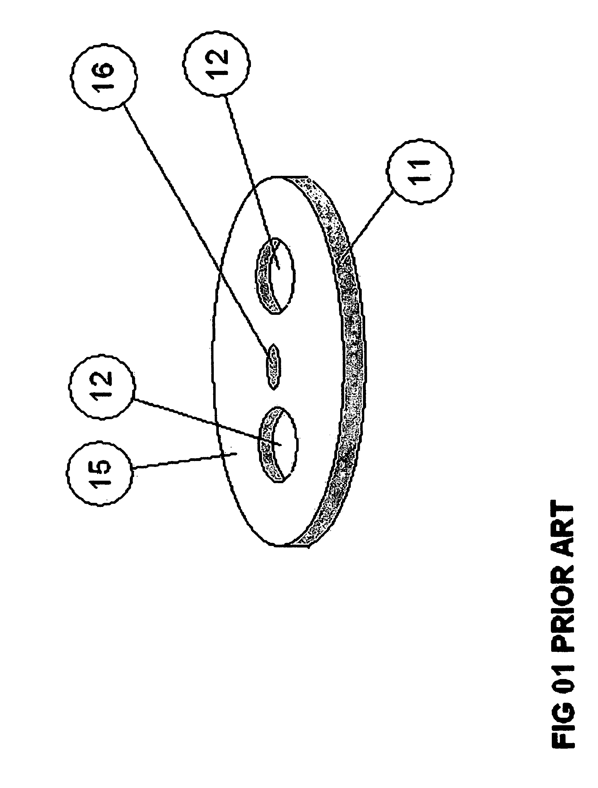
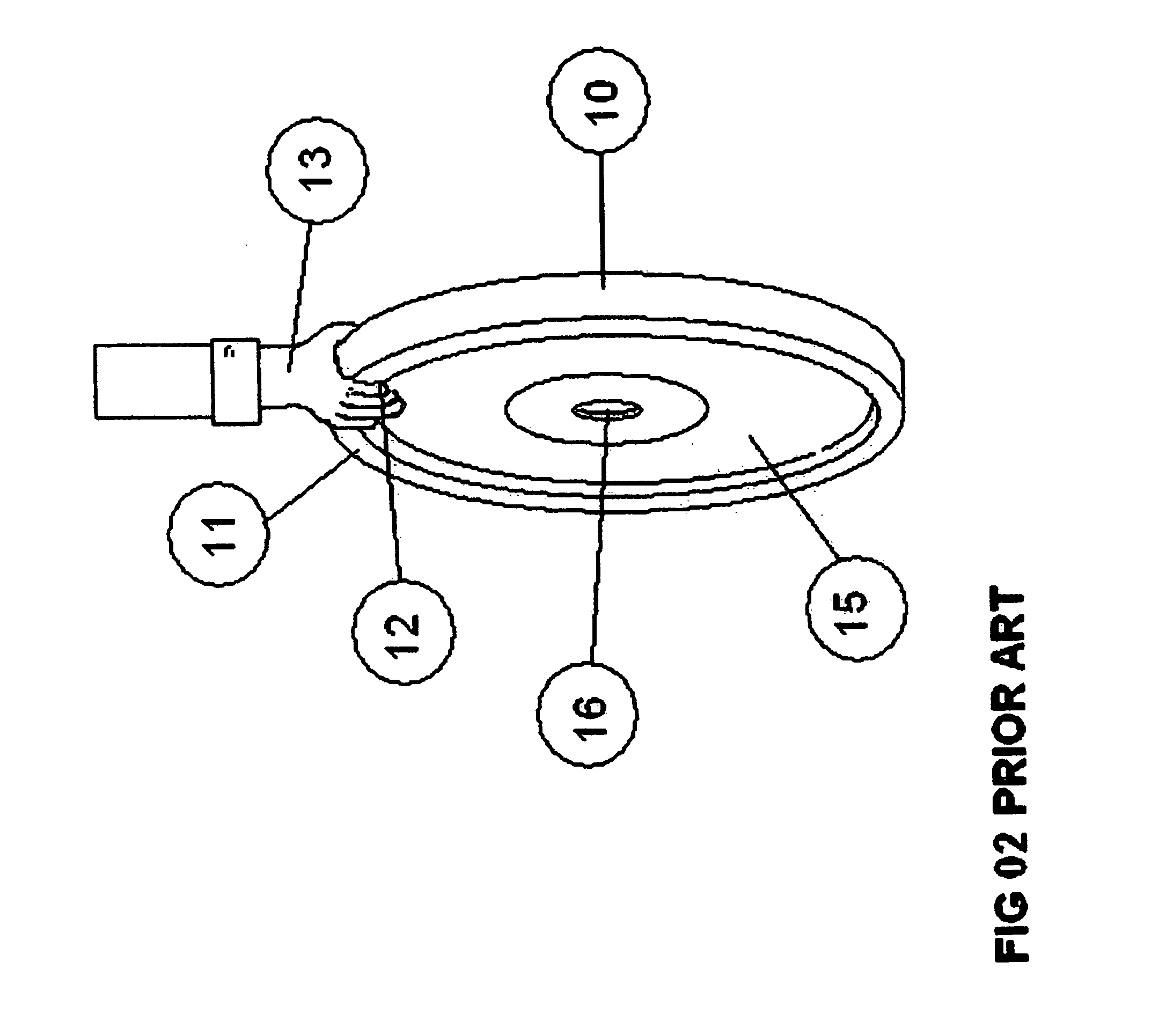
[0011]FIGS. 1 and 2 show free weights barbell plates as they are commonly found in the prior art now.

[0012]FIG. 1 is a top perspective showing common free weight barbell plates with hand openings located directly across from each other.

[0013]FIG. 2 is a top side perspective showing how the lifter's hand engages with the free weight barbell plate as found in the prior art.

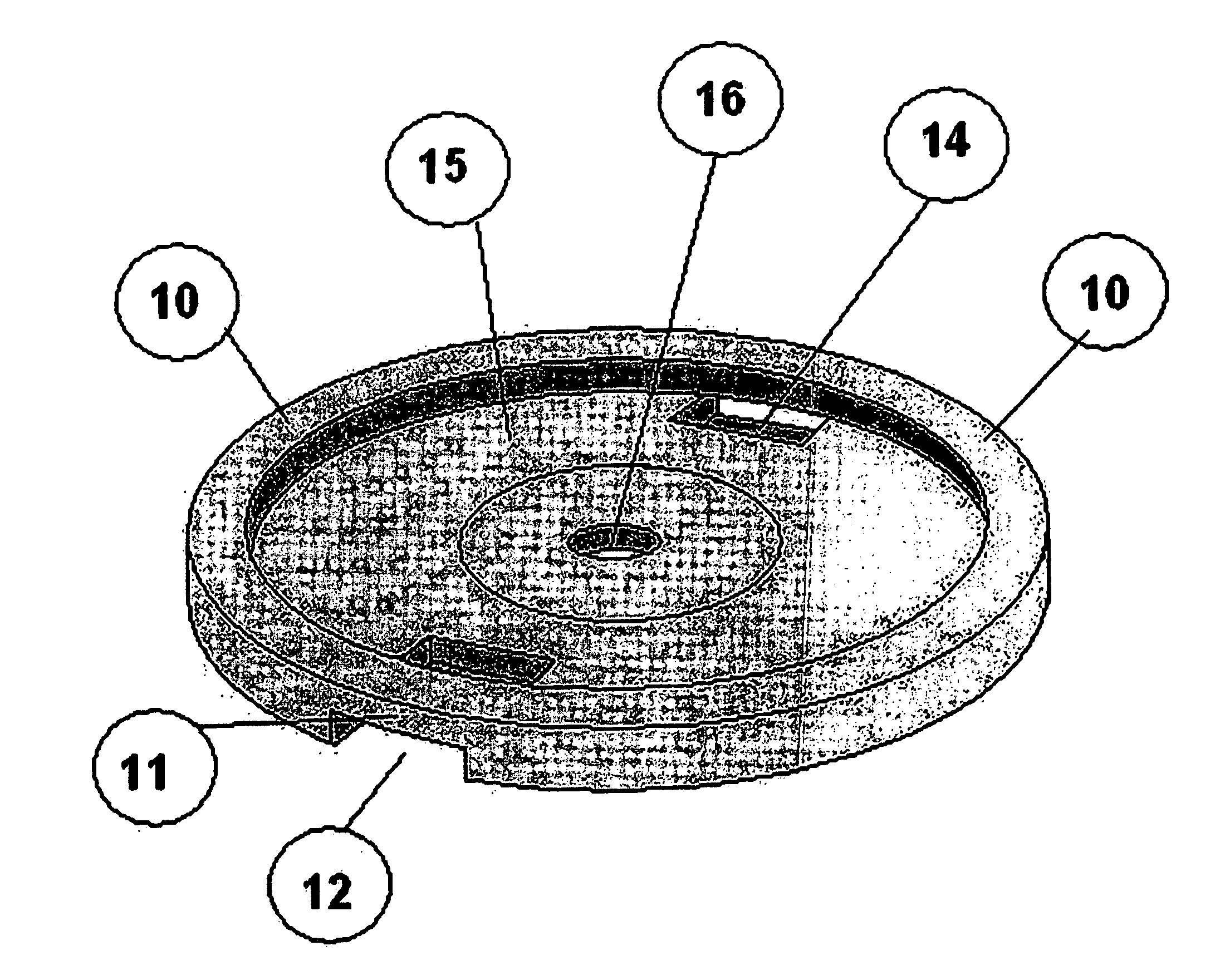
[0014]FIGS. 3-6 show the preferred embodiment of the invention.

[0015]FIG. 3 is a top side perspective showing how the lifter's hand engages with the grip found on the improved free weight barbell plate which is the subject of this invention.

[0016]FIG. 4 is a top side perspective showing the stacking of multiple free weight barbell plates implementing the improved grip.

[0017]FIG. 5 is a top side perspective showing a single improved grip barbell weight plate.

[0018]FIG. 6 is a bottom side perspective showing a single improved grip barbell weight plate.

DETAILED DESCRIPTION—LIST...


PUM


Abstract

This design is placed and or positioned in the periphery of weight creating a semi-protective and semi-recessed area for insertion of a hand or hand like device. The size and shape of the area reduces the potential for unattended and damaging interaction between the hand and its digits or the hand-like devices and the sides of the mass. The curvature of the area along with the width being of sufficient size to facilitate grasping during human interaction of the opening are purposefully designed to ergonomically fit the hand and or hand like device for a plurality of uses. The functionality of the device is to generally distribute the stress and forces applied to the point of interaction between the human user and the contact area of the heavy and or cumbersome object. Substantially increasing the controllability during mass manipulation by purposeful human interaction. The depth of the barbell weight grip must be large enough to accommodate the thickness of the average adult human hand and ranges in most case from 1-3 inches. It may be reduced or enlarged during manufacture as necessary to accommodate non-average size users.

Description

BACKGROUND OF THE INVENTION [0001] The difficulty of lifting and or working with a heavy object increases proportionately with its size. The difficulty of working with a heavy object is compounded when the object is also round in shape and has a smooth finish. This is the situation facing those familiar with the practice of “lifting weights”. Those experienced in lifting weights normally engage in this practice to build-muscle mass. See U.S. Pat. No. 5,137,502 ('502) issued to Anastassi and U.S. Pat. No. 6,746,380 ('380) issued to Lien et. al. for further background and discussion on this subject. [0002] Those engaging in this practice that use “free weights” to train as compared to weight resistance machines, find themselves continually loading and unloading barbells or free weight which are heavy and cumbersome. Many times these weights have either no handle or just a simple hand-hole in the weight to be used as a handle to facilitate picking up the weight and to improve grip on t...

Claims


Application Information

Patent Timeline
Patent Type & Authority Applications(United States)
IPC IPC(8): A63B21/06
CPCA63B21/06A63B2071/0063A63B21/072A63B21/0601
Inventor HAMILTON, JEFF J.
Owner D A G INVENTURES L L C
Learn More