
Measuring system

a technology of measuring system and measuring device, which is applied in the field of measuring system, can solve the problems of heavy and large devices that cannot be brought out, and achieve the effect of ensuring the patient's health sta

Inactive Publication Date: 2006-12-28
NEC CORP
View PDF8 Cites 140 Cited by
  • Summary
  • Abstract
  • Description
  • Claims
  • Application Information

AI Technical Summary

Benefits of technology

The present invention provides a technology for checking one's health at a desired place without needing to visit inspection agencies. The technology includes a portable mobile terminal and a measuring chip that can be easily inserted into the mobile terminal. The measuring chip performs a predetermined operation on a sample introduced to it, and the mobile terminal analyzes the measurement result and provides feedback to the user. The mobile terminal is designed to be easily operated and has a small size and light weight. The measurement system is safe, healthy, and can be used at various places. The mobile terminal has a communication function and can interact with an expert at a remote place to get accurate analysis results. The measurement system is designed to minimize the impact on the user's health from the measurement process. The mobile terminal can be designed to have a simple and small configuration, and the measuring chip can perform multiple processing on the sample. The mobile terminal can transmit the measurement result outside, and analysis results can be obtained from outside without needing to provide analysis function in the mobile terminal. The measurement system is designed to provide accurate analysis results based on the measurement result.

Problems solved by technology

Since a heavy and large device cannot be brought out to a desired place, a measurement system needs to be as small and light as possible.
Further, there is a case where a mechanism for neutralizing a measuring chip needs to be provided because it becomes unsuitable for a mobile sanitarily when disinfectant treatment is not certainly applied to a measuring chip, depending on kinds of samples and measurements.

Method used


Image

  • Measuring system
  • Measuring system
  • Measuring system

Examples


first embodiment

[0083] (First Embodiment)

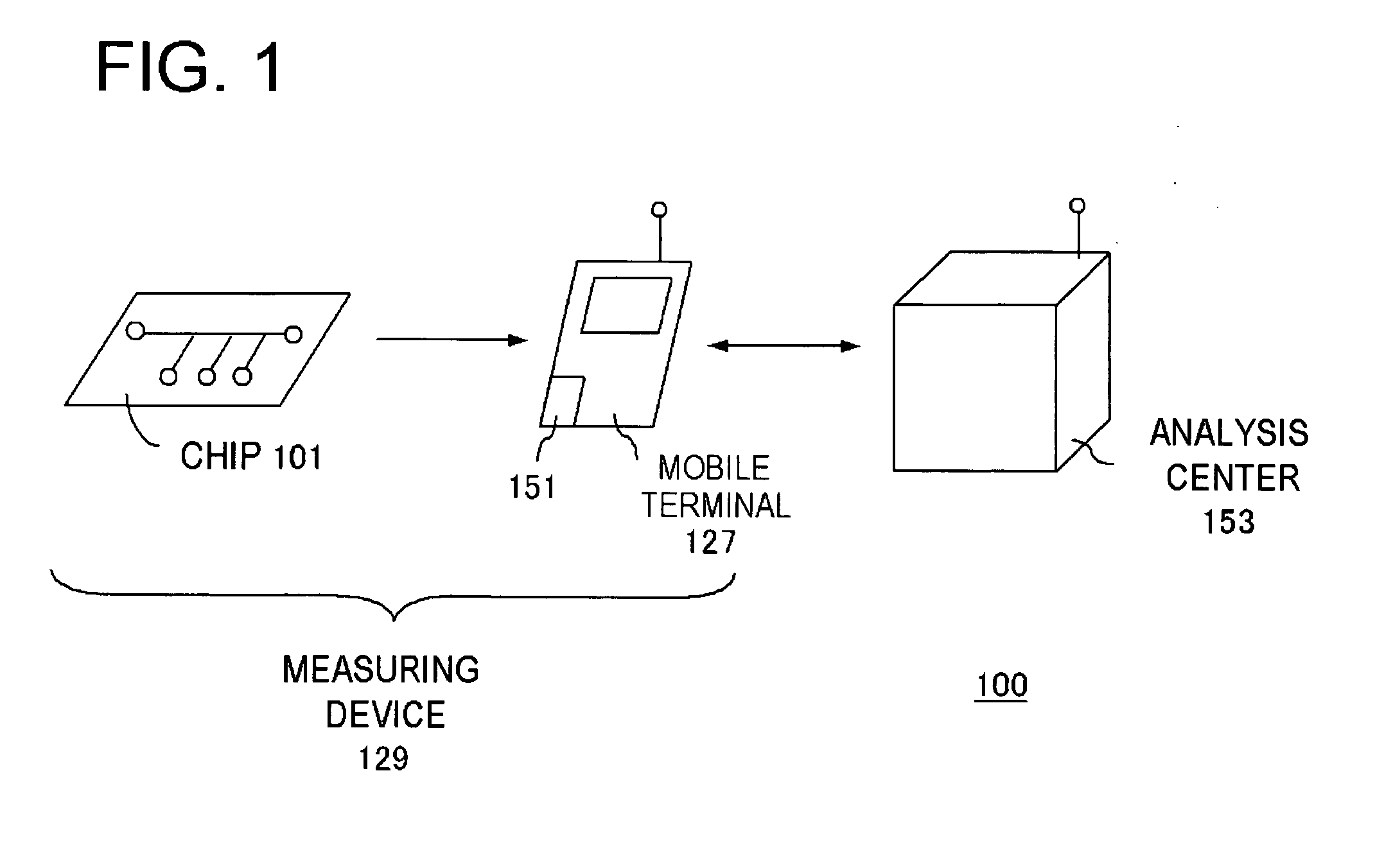
[0084]FIG. 1 is a view showing an inspection system of an embodiment. An inspection system 100 includes a measuring device 129 and an analysis center 153. The measuring device 129 is composed of a chip 101 and a mobile terminal 127 and each component has different function. The inspection system 100 performs measurement on a subject in user's body fluid using the measuring device 129 to examine user's health state.

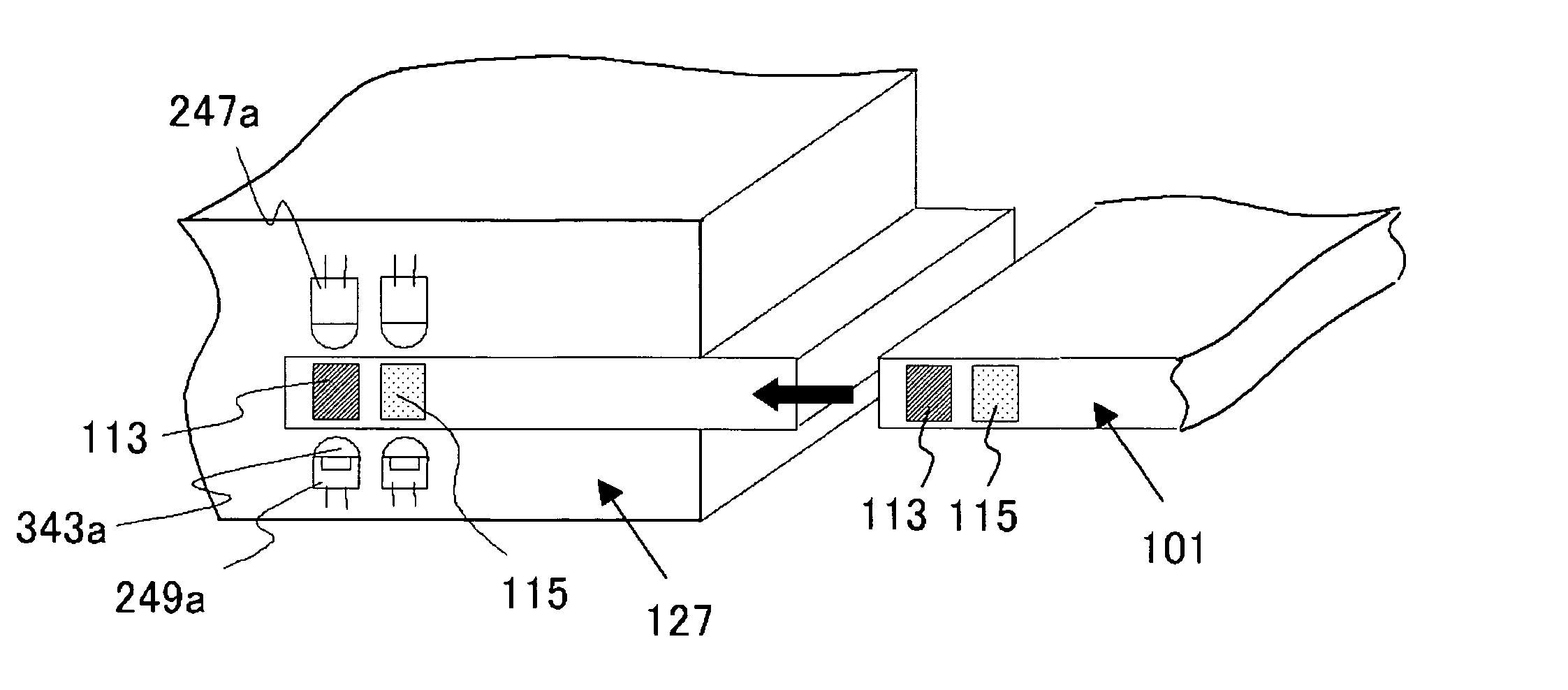
[0085] The mobile terminal 127 may be a mobile phone having communication function, a personal digital assistant (referred to as PDA), or the like. The case where the mobile terminal 127 is a mobile phone will be described below as an example. The mobile terminal 127 includes a measurement unit 151 which measures detection reaction at the chip 101. Here, the measurement unit 151 is, for example, a spectrophotometer, fluorophotometer, charge coupled device (referred to as CCD) camera, or the like. Furthermore, the mobile terminal 127 is configured ...

second embodiment

[0170] (Second Embodiment)

[0171] This embodiment relates to other configuration of chip applicable to the inspection system 100 (FIG. 1) described in the first embodiment. FIG. 18 is a view schematically showing configuration of chip according to this embodiment. A chip 251 of FIG. 18 is a chip which can perform separation and detection of a sample and fundamental configuration is the same as the chip 101 of FIG. 3, however, a separation region 318, a waste solution reservoir 319, a buffer inlet 320, a channel 330, and a mixing unit 348 are further included. Furthermore, a plurality of detection units 323 correspond to the detection unit 113 and the detection unit 115 in the chip of FIG. 3.

[0172] The separation region 318 includes the channel 330 communicated to a channel 109 via the channel 109 and a plurality of fine channels 329 and is configured filter-shaped. The waste solution reservoir 319, which is communicated to the channel 330 and discharges an unnecessary sample, is pro...

third embodiment

[0220] (Third Embodiment)

[0221] This embodiment relates to other configuration of chip applicable to the inspection system 100 (FIG. 1) described in the first embodiment.

[0222]FIG. 26 is a top view showing schematic configuration of a chip 224 according to this embodiment. In the chip 224, the same reference numerals are given to the same constituent elements as in the first and the second embodiments and their description will not be arbitrarily repeated.

[0223] The chip 224 is configured so that a first channel 241 communicated to a sample introducing unit 105 communicates to a second channel 243 via a separation region 245. The second channel 243 communicates to a reservoir 107.

[0224] The first channel 241 communicates to the sample introducing unit 105 in the upstream thereof and to a reservoir 239 in the downstream thereof. Furthermore, a pretreatment unit 231 is formed in the upstream of the separation region 245 and the pretreatment unit 231 communicates to a channel 233. D...


PUM

PropertyMeasurementUnit
widthaaaaaaaaaa
sizesaaaaaaaaaa
thicknessaaaaaaaaaa

Abstract

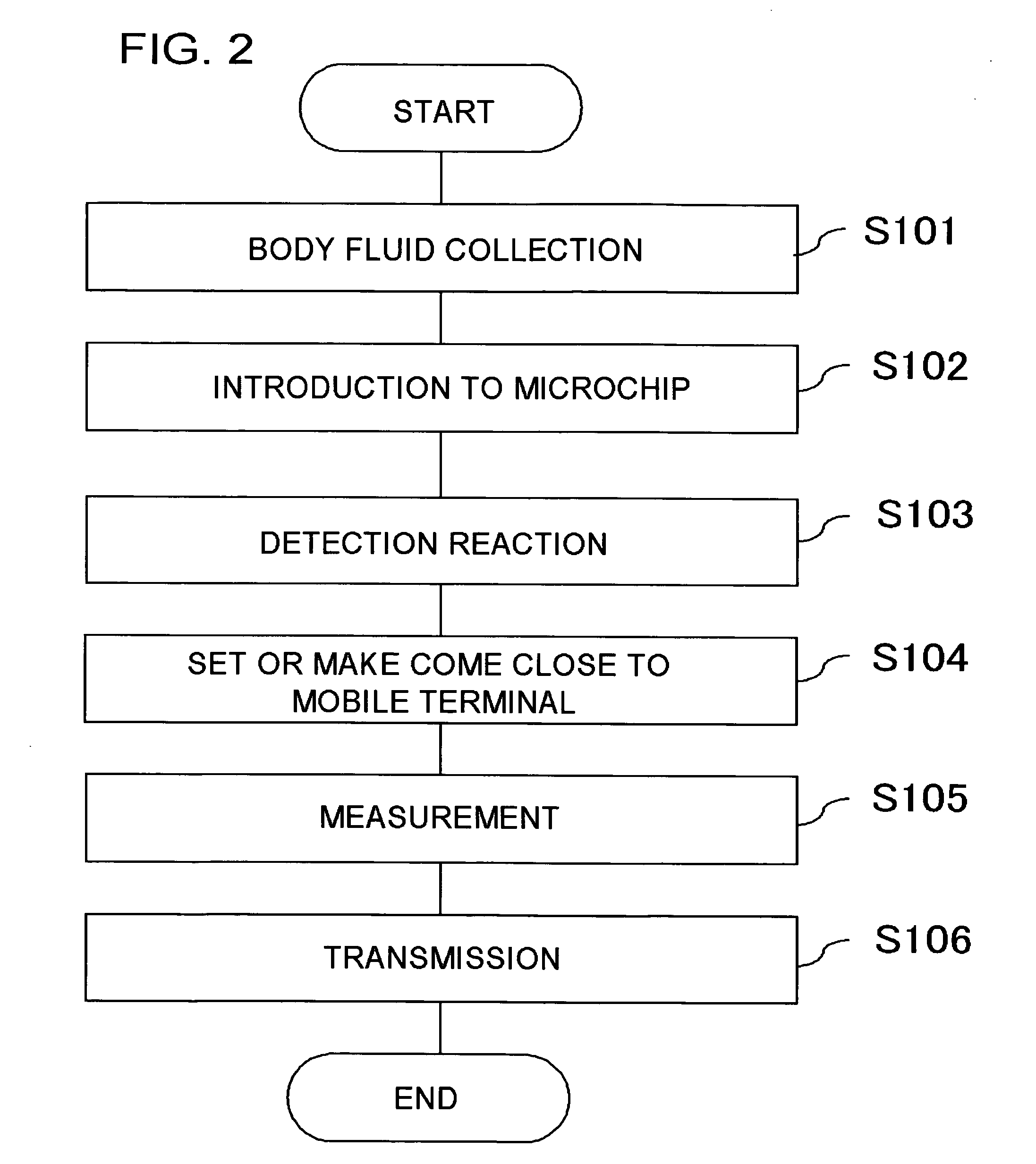
It becomes possible for a user to check his / her own health state at a desired place without visiting inspection agencies. Furthermore, it becomes possible for a user to conveniently check his / her own health state. First, a user collects body fluid to be a measurement object, such as blood, saliva, and urine. Then, the collected body fluid is introduced to the chip (101) as a sample. Then, the sample is made to act on a detection reagent which acts on a specific component in the sample to generate a predetermined detection reaction. This chip (101) is set to the mobile terminal (127). A measurement unit (151) of the mobile terminal (127) measures an amount of a specific component in the sample by means that product of reaction is quantitated by an optical method or the like. The mobile terminal (127) transmits the measurement value to an analysis center (153).

Description

TECHNICAL FIELD [0001] The present invention relates to a measurement system. BACKGROUND ART [0002] In recent years, there has been a lot of interest in health management based on data. Furthermore, there are those who need to continuously obtain their biological data and check their health states. Conventionally, when such persons visit inspection agencies and undergo inspection, there are constraints in time and cost and therefore the busier persons are, the less opportunity they undergo inspection. Consequently, development of technology capable of readily checking of one's own health state without visiting inspection agencies has been required. [0003] Consequently, a health management support system which automatically collects biological data at a health management center in a remote place is proposed (Patent Document 1). According to a technology described in the aforementioned document, a person to be inspected provides an exclusive terminal at home and thereby can transfer m...

Claims


Application Information

Patent Timeline
Patent Type & Authority Applications(United States)
IPC IPC(8): G01N21/00A61B5/00G01N1/02
CPCA61B5/0002A61B5/14532A61B2562/0295A61B5/6898A61B5/1455G01N2001/021G01N21/8483Y02A90/10
Inventor IIDA, KAZUHIRO
Owner NEC CORP
Learn More