
Display device having improved properties

Active Publication Date: 2006-12-28
NEOGRAF SOLUTIONS LLC
View PDF49 Cites 22 Cited by
  • Summary
  • Abstract
  • Description
  • Claims
  • Application Information

AI Technical Summary

Benefits of technology

[0023] Accordingly, it is an object of the present invention to provide a frame for a display device such as a plasma display panel, a liquid crystal display or the like, which is lightweight and structurally sound.
[0024] It is another object of the present invention to provide a display device having improved properties, including improved luminosity, reduced image sticking, reduced average screen temperature and improved temperature uniformity.
[0025] Still another object of the present invention is to reduce the screen temperature of a display panel in the bottom third of the panel.

Problems solved by technology

The heat generated in the discharge cells is transferred to the glass forming the base plates, but heat conduction in directions parallel to the panel face is difficult because of the poor thermal spreading properties of the glass base plate material.
Further, since the temperature difference between activated and nonactivated discharge cells can be high, and the temperature difference between discharge cells generating white light and those generating darker colors can also be high, a stress is applied to the panel unit, causing the conventional plasma display panel to be prone to cracks and breakage.
Thus, those cells having large voltages for activation become more susceptible to thermal deterioration and tend to exacerbate the breakage problem of the panel unit of the plasma display panel.
Moreover, the luminosity of the panel can also suffer as panel temperature rises, especially when temperature is not uniformly distributed.
The backlights for LCD displays, such as LEDs (light emitting diodes), CCFLs (cold cathode fluorescent light or lamp) and FFPs (flat fluorescent light or lamp), present similar issues with respect to heat generation as do emissive displays, such as PDP's.
The graphite heat spreaders of Tzeng are positioned between a heat generating electronic component and, advantageously, a heat sink, to increase the effective surface area of the heat generating component; the Tzeng patent does not address the specific thermal issues occasioned by display devices.
Heat passing from these electronic components contributes to uneven temperature distributions created on the panel unit itself, which adversely affects the image presented on the display panels.
A support member such as this can weigh about 10 pounds or more, and can be expensive and difficult to construct, due to certain flatness requirements, the need for many threaded mounting features for the electronics, and the high cost of high thermal conductivity aluminum sheet.
This can mean more power being sent to the display, which increases the thermal load on the system and requires additional heat dissipation capabilities within the display units.
Active cooling solutions, such as fans and / or heat pipes, are undesirable due to unreliability, noise, and the fact that they contribute negatively to the cost and weight of the system.
In addition to increasing brightness and luminous efficiency of the displays, display manufacturers are also under increasing pressure to produce larger panel sizes, which tends to increase the weight of the support member proportionately.
Moreover, display panels having conventional frame systems exhibit undesirably high image sticking and undesirably low luminosity, exacerbating the issues detailed above.
Moreover, even though conventional frame systems are intended to ease thermal issues for the panels, non-uniform temperature distribution in a display panel remains an issue, as does the average screen temperature and the temperature in the bottom third of the screen, where temperature-increasing graphics often appear.

Method used


Image

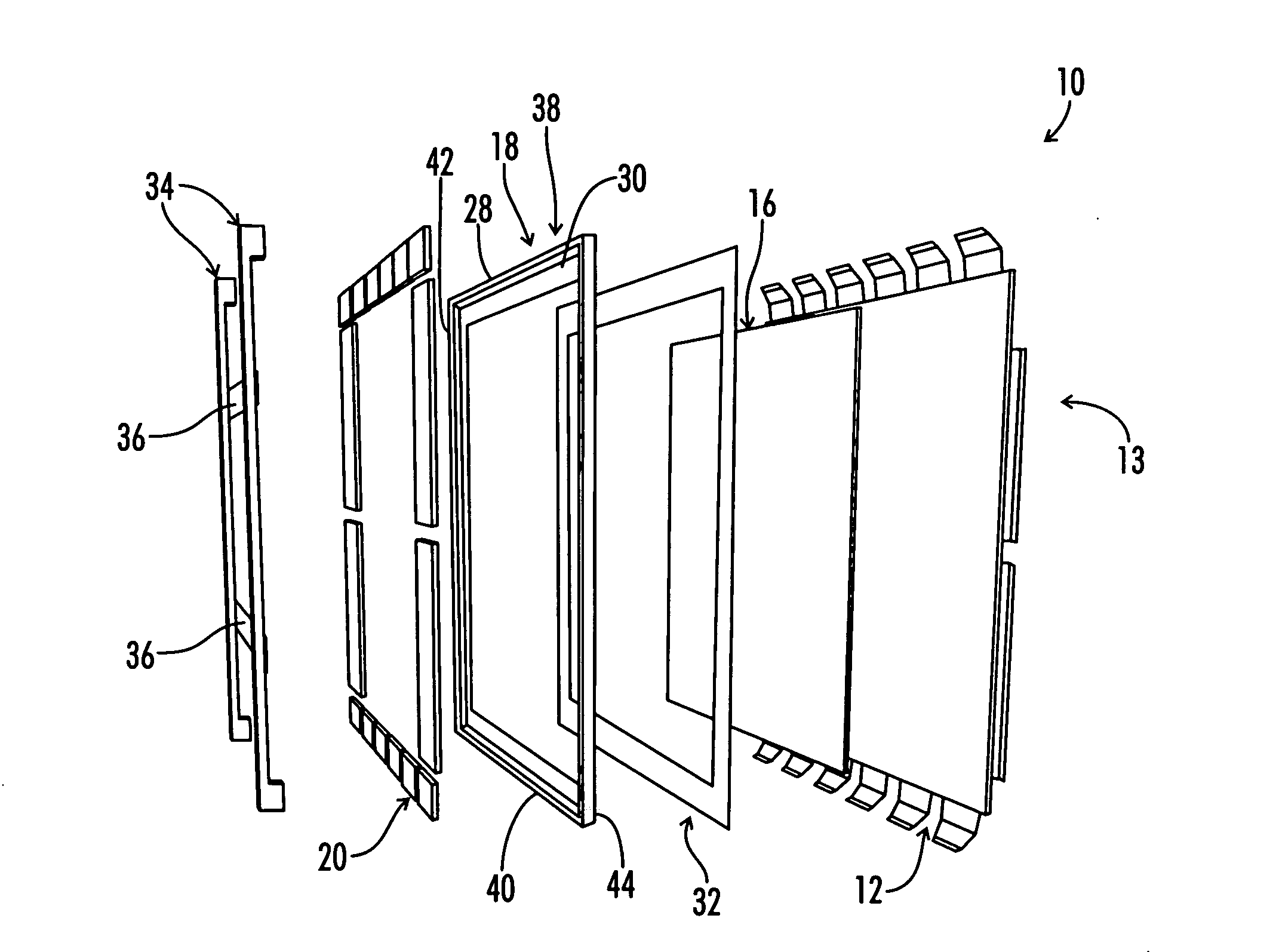
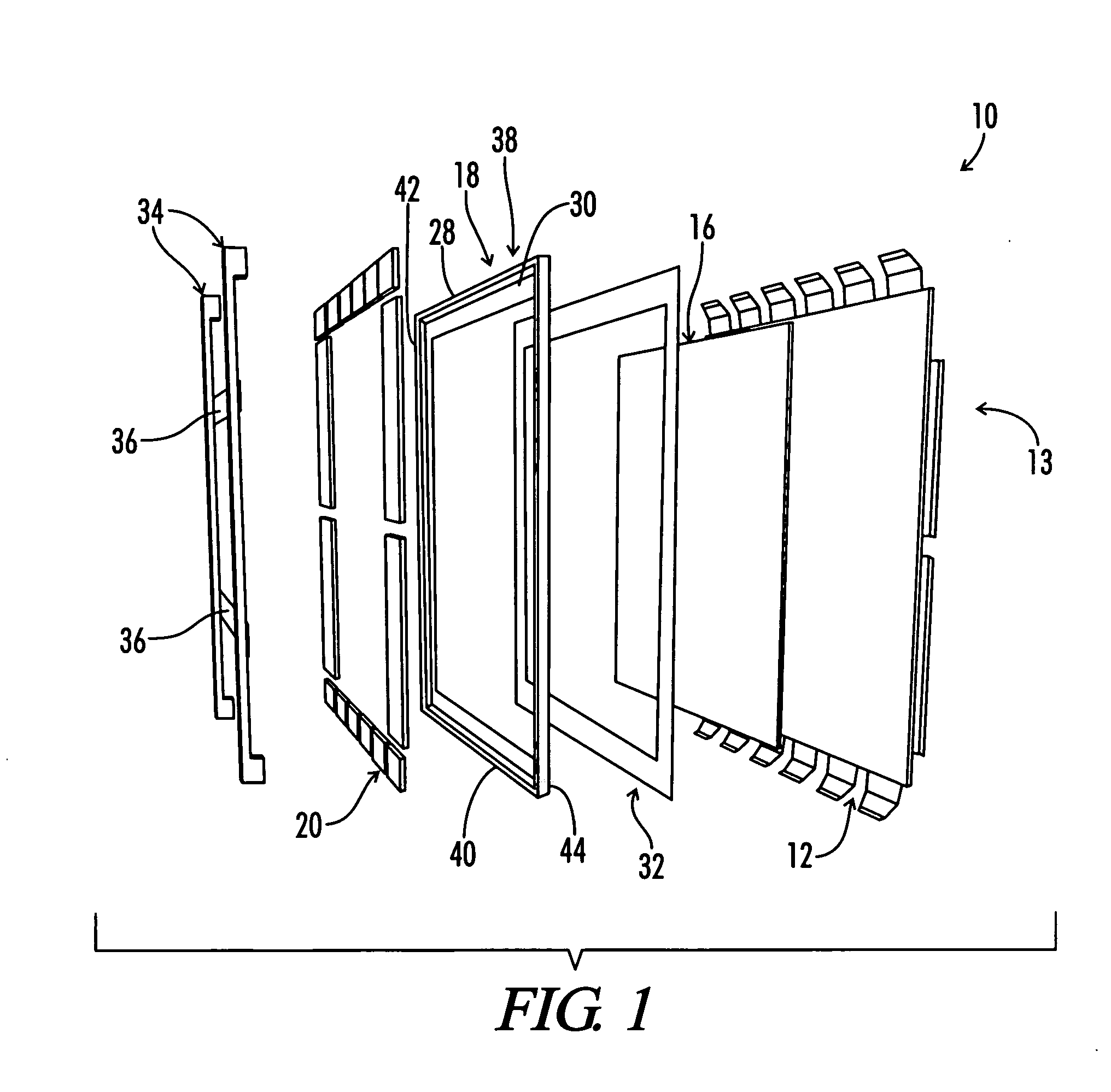
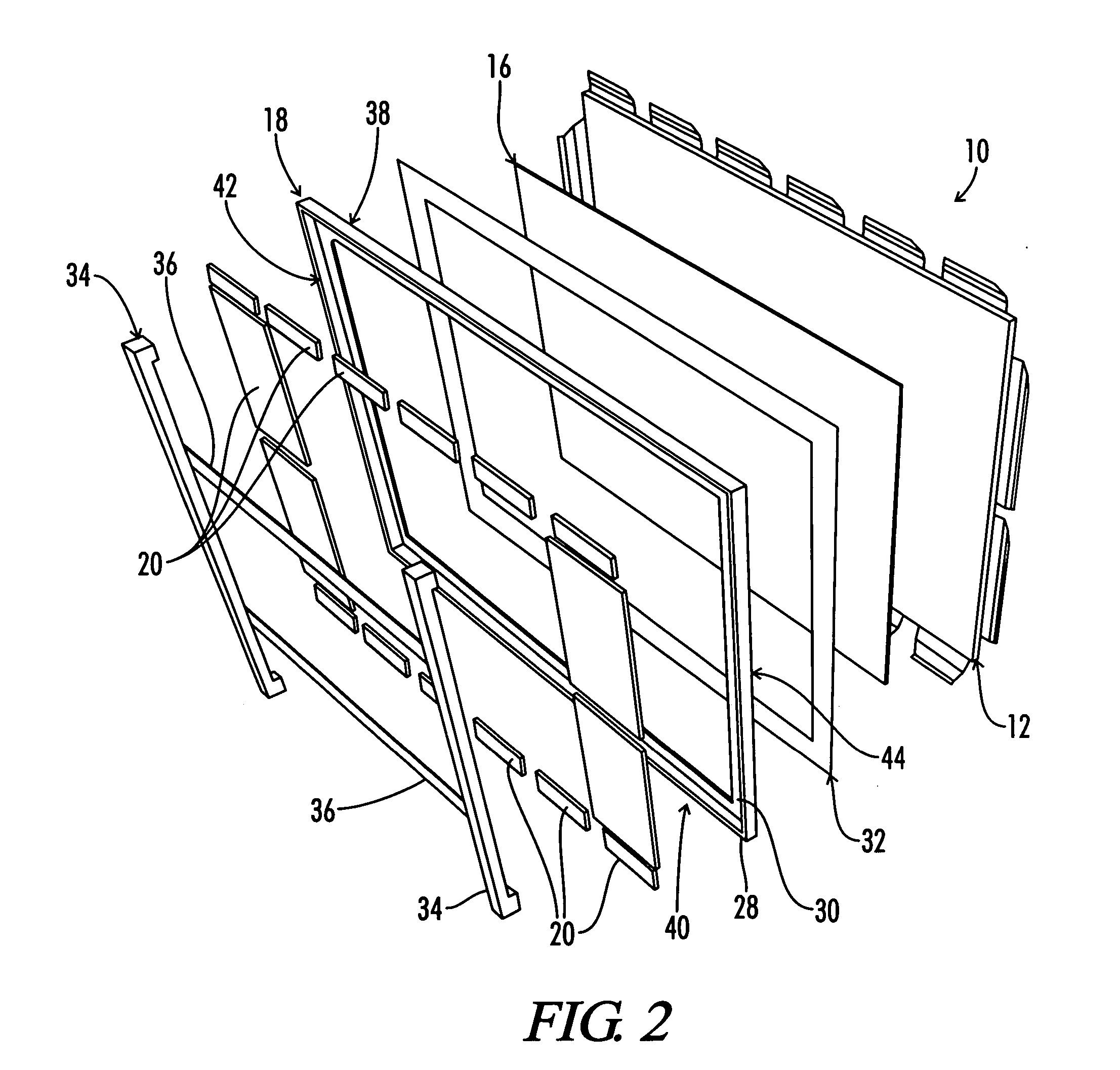
  • Display device having improved properties
  • Display device having improved properties
  • Display device having improved properties

Examples


example one

[0122] A 42″ commercial PDP (Hitachi Ultravision HD42T51) is thermally tested in the as-received condition. Thermal characterization of the panel is conducted using an infrared camera (IR Flexcam® infrared camera) focused on the front of the PDP. The testing conducted is under conditions of 100 % illumination (full white).

[0123] The same PDP is then dismantled and the existing aluminum chassis and steel subframe (FIG. 17) replaced by the inventive frame as shown in FIG. 18. Thermal testing is then repeated, with results reported in Table 1.

TABLE 1AverageFull WhiteTemperatureChassisAverageRise inWeightTemperatureBottom ZonelbsRise ° C.° C.State of the Art23.928.125.0Optimized Frame12.624.520.6Improvement11.33.64.4

[0124] As shown in Table 1, a weight reduction of 11.3 lbs is achieved and an average temperature reduction of 3.6° C. is achieved. This reduction in temperature is important because, as shown in Example Two, luminance and image sticking, both important display parameters...

example two

[0127] To demonstrate that lower temperatures improve luminosity and reduce image sticking, both important display parameters, an experiment is conducted to vary the PDP screen temperature over a wide range and measure corresponding luminance and image sticking trends with temperature. A PDP screen is split into three zones with, respectively, no heat spreader, a low thermal conductivity (approximately 1 W / m° K) acrylic thermal interface material bonded to the aluminum chassis, and a high in-plane thermal conductivity (approximately 400 W / m° K) graphite heat spreader contacting the PDP glass, as shown in FIG. 19. A white spot test pattern is then set up with two spots / zone, as shown in FIG. 20, and the temperature of each spot measured every two minutes as the PDP panel heats up. A typical IR image is shown in FIG. 21 with a chart of temperature versus time shown in FIG. 22. The advantage of the graphite spreader in minimizing temperature rise in the white spot area is apparent. Not...


PUM


Abstract

An image display device having improved properties, comprising an image display panel, heat dispersion material positioned proximate to the image display panel, an open frame positioned proximate to the heat dispersion material opposite the image display panel, and a plurality of electronic components engaging the open frame, the image display device exhibits a support factor of less than about 375 mm-W / m° K.

Description

RELATED APPLICATION [0001] This application is a continuation-in-part of copending and commonly assigned U.S. patent application having Ser. No. 11 / 167,935, entitled “Optimized Frame System For A Display Device,” filed in the names of Shives et al. on Jun. 27, 2005, the disclosure of which is incorporated herein by reference.TECHNICAL FIELD [0002] The present invention relates to a display device, such as a plasma display panel (PDP), a liquid crystal display (LCD), and the like, having improved luminosity, decreased image sticking and improved temperature uniformity, occasioned by a unique support structure for the device. BACKGROUND OF THE ART [0003] A plasma display panel is a display apparatus which contains a plurality of discharge cells, and is constructed to display an image by applying a voltage across electrodes discharge cells thereby causing the desired discharge cell to emit light. A panel unit, which is the main part of the plasma display panel, is fabricated by bonding...

Claims


Application Information

Patent Timeline
IPC IPC(8): H01J17/49H01J61/52H01J17/16
CPCG02F1/133385H05K7/20963H01J11/10G02F1/133603G02F1/1333G02F1/133308G02F1/133382H01J9/241H01J17/28H01J17/49
Inventor SHIVES, GARY D.HOFFERT, GERALDVARELA, WILLIAM
Owner NEOGRAF SOLUTIONS LLC
Learn More