
In-case computer charging system

a charging system and computer technology, applied in the field of portable electronic device recharge, can solve the problems of wasting considerable funds, dead batteries or poor contacts, and relatively foolproof charging, and achieve the effect of reducing shorting

Inactive Publication Date: 2006-12-28
JACKSON SHAUN +1
View PDF6 Cites 20 Cited by
  • Summary
  • Abstract
  • Description
  • Claims
  • Application Information

AI Technical Summary

Benefits of technology

[0006] Typically the electrical contacts allow a battery in the case or in the device to be recharged while device is enclosed. To reduce shorting, one or more of the electrical contacts may protrude from the case, or one or more of the electrical contacts may be recessed. One or more of the electrical contacts may be adapted to magnetically engage with a corresponding set of electrical contacts, and a light may be provided on the case or the docking station to indicating that electrical current is flowing to the device through the case.

Problems solved by technology

One of the problems with these arrangements is that students, particularly younger children, can drop the computer while removing or returning the device from and to its storage compartment, thereby costing the school considerable funds.
Problems may also arise in the wiring associated with plugging and unplugging the recharger, resulting in dead batteries or poor contacts.
The need remains, therefore, for a system which is relatively fool-proof in terms of charging, while, at the same time, protecting expensive devices such as laptop computers.

Method used


Image

  • In-case computer charging system
  • In-case computer charging system
  • In-case computer charging system

Examples


Embodiment Construction

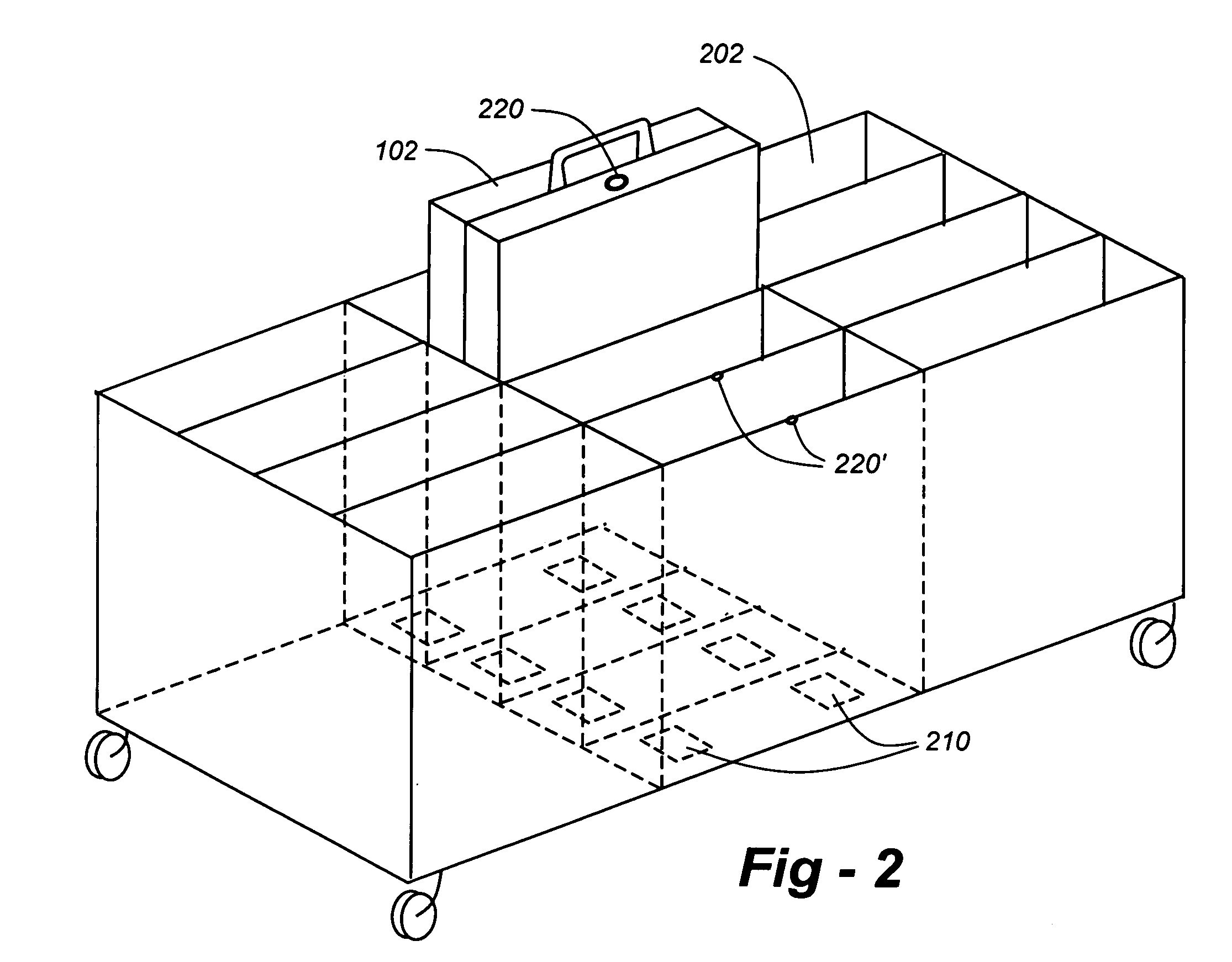
[0014] Broadly, this invention resides in cases and corresponding storage facilities that enable a portable electronic device to be recharged while enclosed in that case, thereby protecting the device during periods when it is not in use. The invention is applicable to all types of portable electronic devices, including laptop, notebook and palm-top computers, as well as telecommunications devices, video players and music players.

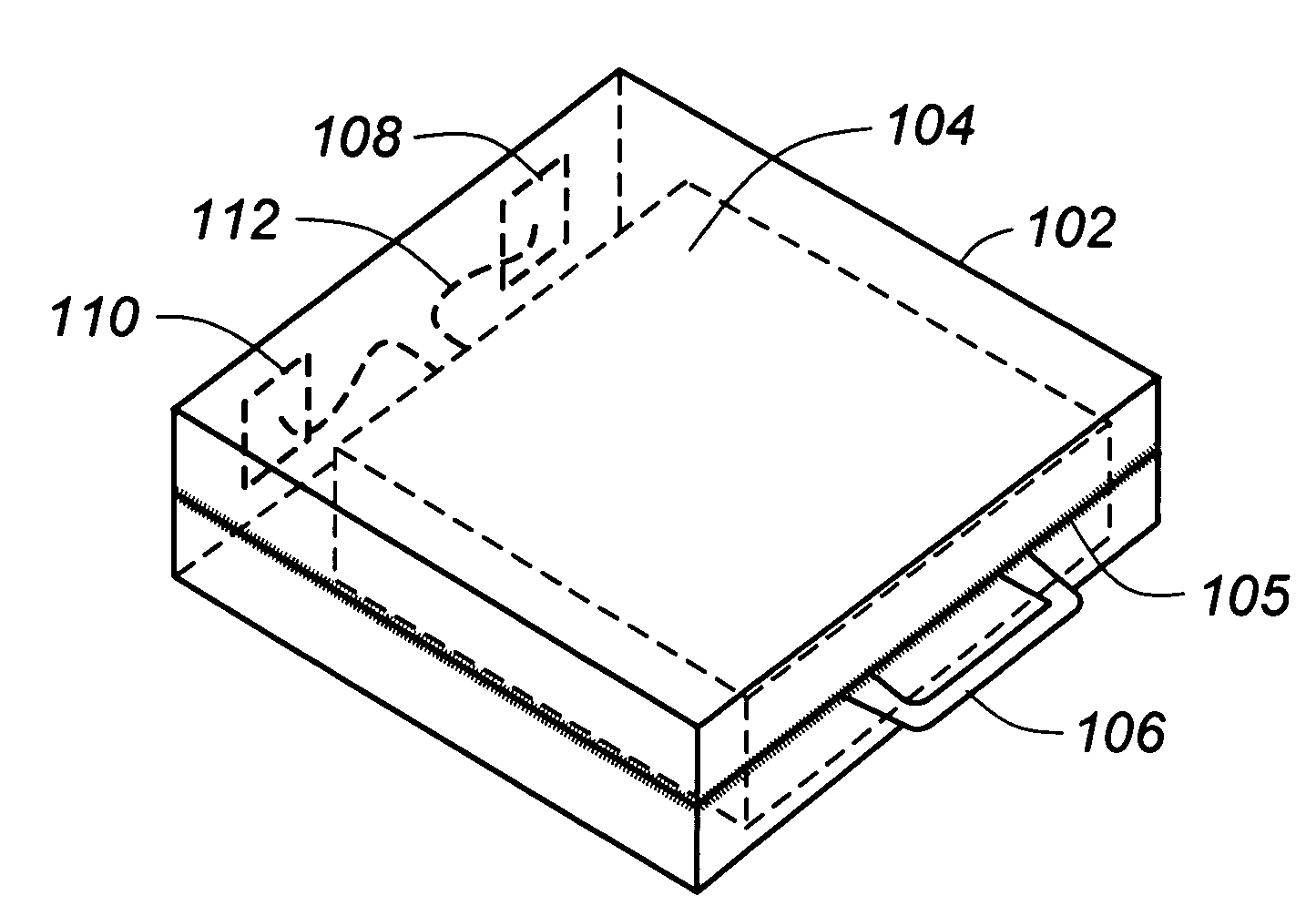
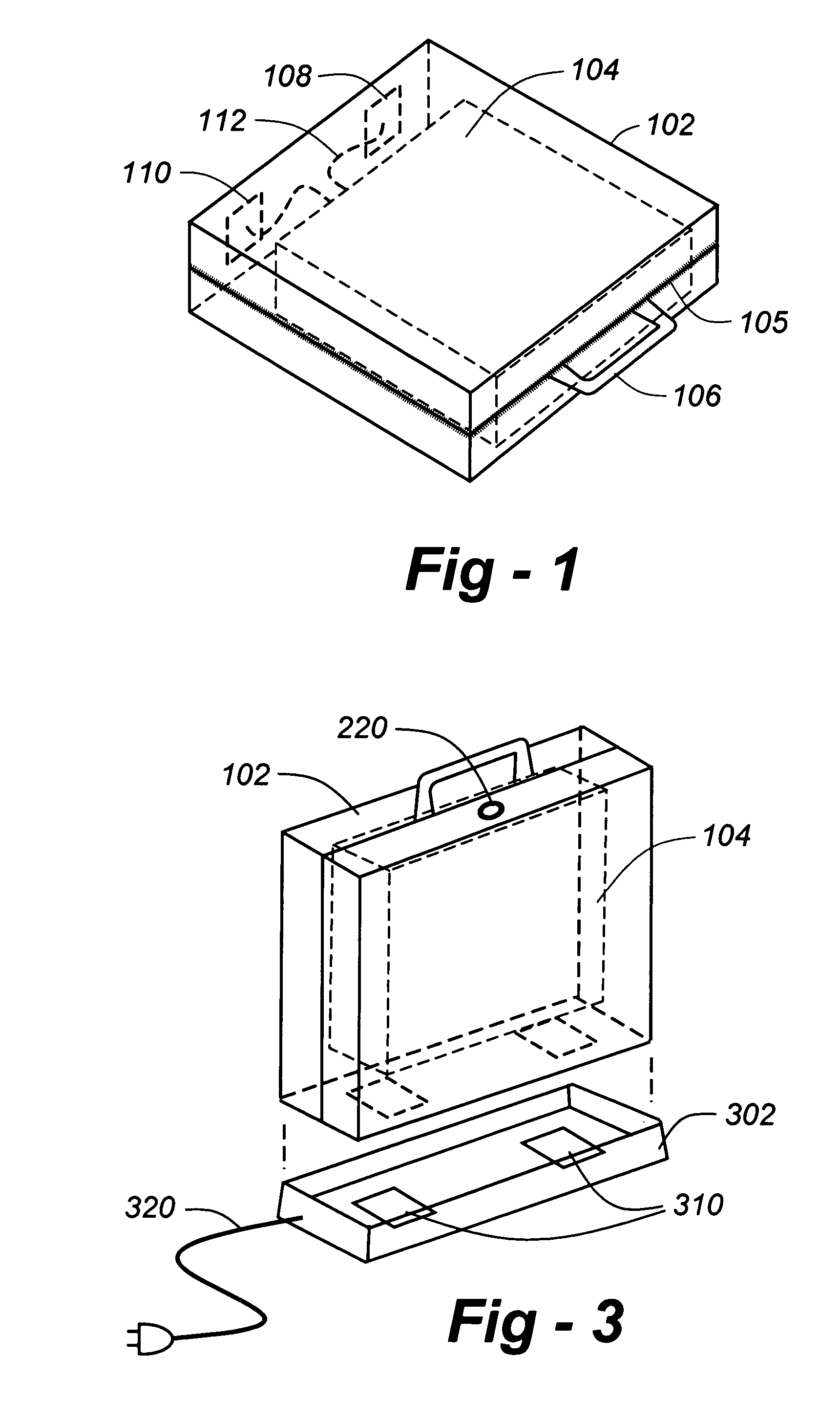
[0015] A preferred embodiment is shown in FIG. 1. The case, 102, which may be of any soft or hard design, includes contacts 108, 110, preferably on one of the side edges of the case. The contacts 108, 110 interconnect to the device shown in broken-line form at 104, through appropriate electrical interconnects 112. In the preferred embodiment two or more such contacts are provided, depending upon the make / model of the enclosed device, though an embodiment with a single contact is possible if at least a portion of the outside surface of the case is sufficien...


PUM

PropertyMeasurementUnit
Poweraaaaaaaaaa
Electrical currentaaaaaaaaaa

Abstract

A case configured to enclose a portable electronic device includes a plurality of externally accessible electrical contacts, enabling electrical current to flow to or from the device while enclosed in the case. The invention is applicable to all types of portable devices, including laptop, notebook and palm-top computers, as well as telecommunications devices, video players and music players. Typically the electrical contacts allow a battery in the case or in the device to be recharged while device is enclosed. An adaptor cable may be provided between the device and the electrical contacts so that the same or similar case may be used with different model devices from different manufacturers. For greater ‘universality,’ a voltage-changing adaptor cable may be provided within the case between the device and the electrical contacts. The system may further include a docking bay to receive the case, the docking bay having a set of electrical contacts configured to electrically engage with the contacts on the case. Such a docking bay may take the form of a charging stand, a cart with one or more slots or compartments, or a locker with a door and a storage compartment.

Description

REFERENCE TO RELATED APPLICATIONS [0001] This application claims priority to U.S. Provisional Patent Application Ser. No. 60 / 684,894, filed May 26, 2005, the entire content of which is incorporated herein by reference.FIELD OF THE INVENTION [0002] This invention relates generally to the recharging of portable electronic devices and, in particular to systems and methods for recharging such devices while enclosed in cases according to the invention. BACKGROUND OF THE INVENTION [0003] It is becoming increasingly popular to provide schoolchildren with laptop computers which they obtain from a cart or locker in the classroom. U.S. Pat. Nos. 6,008,621 and 6,218,796 show such storage carts. Some of these notebook computer carts are are also commercially available from various sources. [0004] One of the problems with these arrangements is that students, particularly younger children, can drop the computer while removing or returning the device from and to its storage compartment, thereby co...

Claims


Application Information

Patent Timeline
IPC IPC(8): F27D11/00
CPCB32B5/024H05B2203/017B32B5/26B32B2250/03B32B2250/20B32B2250/40B32B2255/02B32B2255/205B32B2260/023B32B2260/046B32B2262/101B32B2262/106B32B2307/54B32B2603/00B64D15/12G06F1/1628G06F1/1632H05B3/347H05B2203/007H05B2203/014B32B5/12H05B3/20
Inventor JACKSON, SHAUNZADVINSKIS, MARK
Owner JACKSON SHAUN
Learn More