
Fluorescent pattern forming article, recording medium, security medium, and recording method

a technology of fluorescence pattern and recording medium, which is applied in the field of fluorescent pattern forming articles, recording mediums, security mediums, and recording methods, can solve the problems of degrading security, difficult to realize automated treatment, and difficult to actually realize methods, and achieve convenient detection and excellent security.

Inactive Publication Date: 2006-12-21
KK TOSHIBA
View PDF16 Cites 16 Cited by
  • Summary
  • Abstract
  • Description
  • Claims
  • Application Information

AI Technical Summary

Benefits of technology

[0009] Therefore, an object of the present invention is to provide a fluorescent pattern forming article which is excellent in security and can be conveniently detected.
[0015] According to a sixth aspect of the present invention, there is provided a recording method for performing recording of information onto a fluorescent pattern forming article comprising a first layer containing a metal ion; and a second layer disposed facing the first layer and containing a ligand coordinating with the metal ion contained in the first layer and enabling an intensity of fluorescence based on the metal ion to be changed; the method comprising a step of externally applying at least one kind of energy selected from heat, stress and light to the fluorescent pattern forming article to enable the ligand of the second layer to be coordinated with the metal ion of the first layer, thereby changing the intensity of fluorescence to perform the recording of information.

Problems solved by technology

However, the multicoloration leads to the requirement of sophistication of detector and raises the problem that it is impossible to realize automated treatment if the detection is required to be performed by one's eyes.
However, the method seems to be accompanied by various problems that if the contrast ratio is to be enhanced by adjusting the concentration of fluorescent substance, various kinds of ink are prepared depending on the concentration of fluorescent substance, thus making the method very difficult to actually realize, and if the contrast ratio is to be enhanced by adjusting the quantity of ink to be applied, the configuration of ink may be reflected on the printed surface, thus degrading the security.
Therefore, the deterioration, if any, of security mentioned above may raise a serious problem.

Method used


Image

  • Fluorescent pattern forming article, recording medium, security medium, and recording method
  • Fluorescent pattern forming article, recording medium, security medium, and recording method
  • Fluorescent pattern forming article, recording medium, security medium, and recording method

Examples


first embodiment

[0051] This first embodiment is characterized in that a distribution of the intensity of fluorescence is caused to generate as energy of heat or stress is externally applied to a fluorescent pattern forming article.

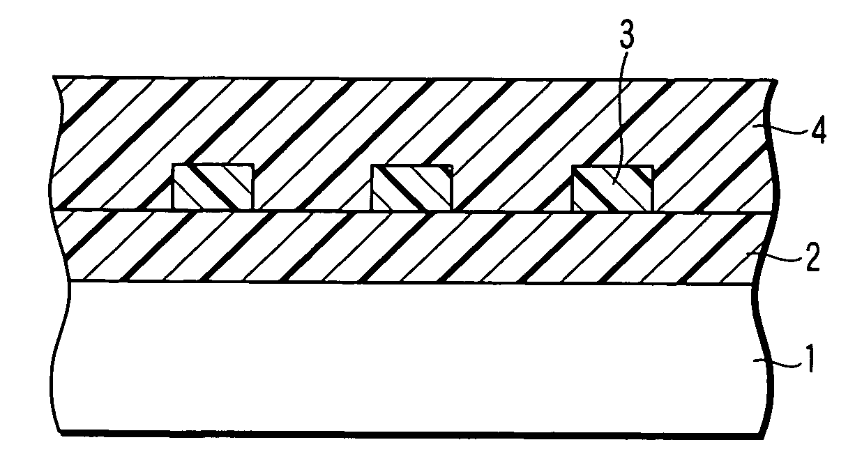
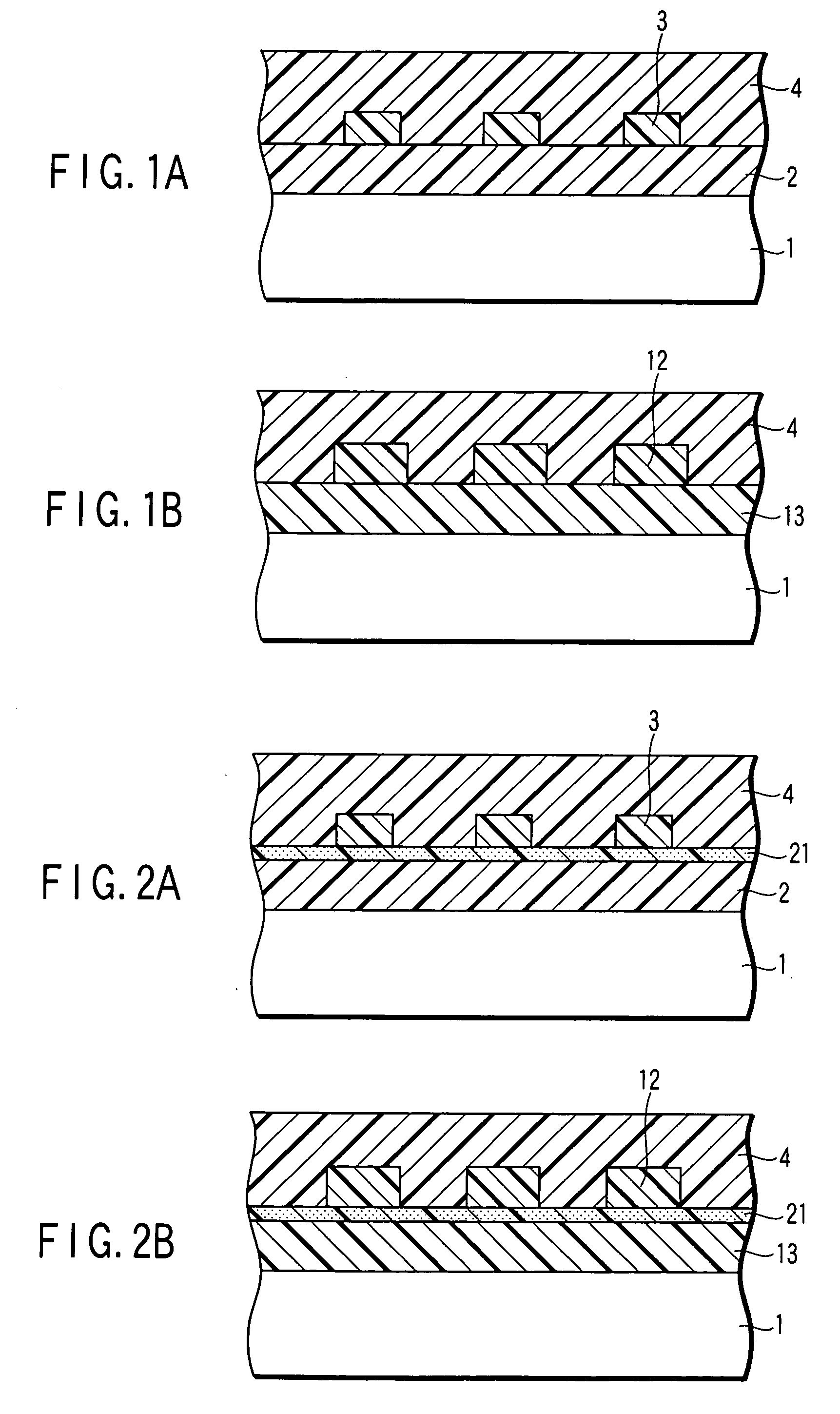
[0052]FIGS. 1A and 1B respectively illustrates a cross-sectional view of the structure of the fluorescent pattern forming article according to this embodiment.

[0053] As shown in FIG. 1A, on a substrate 1 employed as a base body and formed of paper, polyethylene terephthalate (PET) resin, acrylic resin, polycarbonate resin, aluminum foil, glass, etc., there is laminated a metal ion-containing resin layer 2 formed, as a first layer, of a transparent resin containing therein a metal ion (including a metallic complex). Although trivalent Eu ion is incorporated as a metal ion in this metal ion-containing resin layer 2, this Eu ion is incorporated therein in a state of Eu complex wherein an acetylacetonato derivative (β-diketone derivative) as represented by the following for...

second embodiment

[0084] This second embodiment is characterized in that a partitioning layer (separator layer) is interposed between the metal ion-containing resin layer and the ligand-containing resin layer. FIGS. 2A and 2B respectively illustrates a cross-sectional view of the structure of the fluorescent pattern forming article according to this second embodiment. The components or portions which are the same as those of the FIGS. 1A and 1B will be identified by the same reference numerals in this second embodiment.

[0085] As shown in FIG. 2A, a partitioning layer (separator layer) 21 is interposed between the metal ion-containing resin layer 2 and the ligand-containing resin layer 3 for separating these layers from each other. More specifically, this partitioning layer 21 is interposed between the metal ion-containing resin layer 2 and the ligand-containing resin layer 3 and also between the metal ion-containing resin layer 2 and the protective film 4. This partitioning layer 21 plays a role of ...

third embodiment

[0091] This third embodiment is characterized in that a partitioning layer which is interposed between the metal ion-containing resin layer and the ligand-containing resin layer is patterned in conformity with the configuration of the pattern of the metallic ion-containing resin layer or of the ligand-containing resin layer.

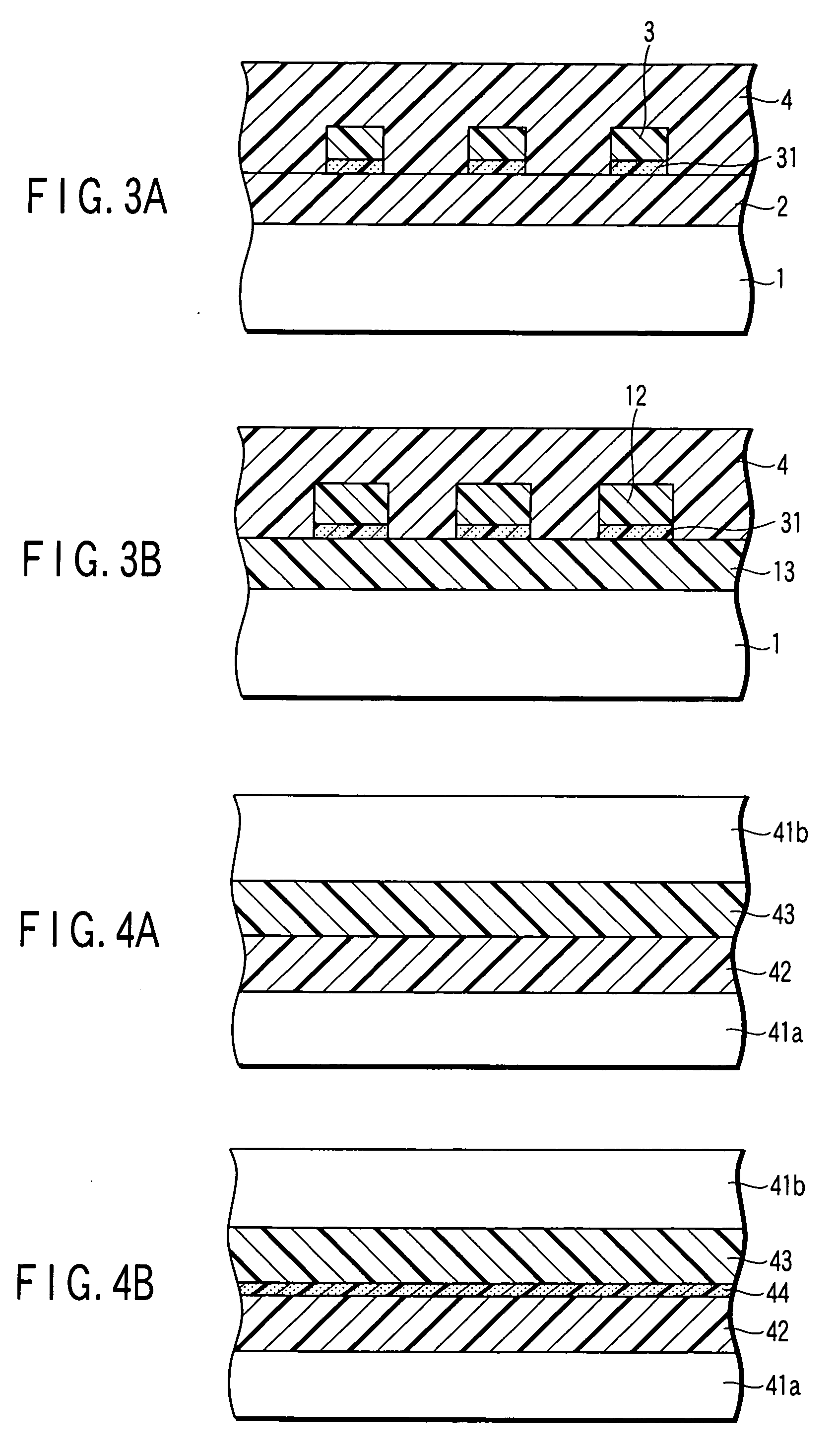
[0092]FIGS. 3A and 3B respectively illustrates a cross-sectional view of the structure of the fluorescent pattern forming article according to this third embodiment. The components or portions which are the same as those of the FIGS. 1A and 1B will be identified by the same reference numerals in this third embodiment.

[0093] As shown in FIG. 3A, a partitioning layer (separator layer) 31 is interposed between the metal ion-containing resin layer 2 and the ligand-containing resin layer 3 for separating these layers from each other. This partitioning layer 31 is selectively formed in conformity with the regions where the ligand-containing resin layer 3 is formed. A...


PUM

PropertyMeasurementUnit
stressaaaaaaaaaa
pressureaaaaaaaaaa
temperatureaaaaaaaaaa

Abstract

A fluorescent pattern forming article including a first layer containing a metal ion, and a second layer disposed facing the first layer and containing a ligand coordinating with the metal ion contained in the first layer to thereby enable an intensity of fluorescence based on the metal ion to be changed.

Description

CROSS-REFERENCE TO RELATED APPLICATIONS [0001] This application is based upon and claims the benefit of priority from prior Japanese Patent Application No. 2005-176427, filed Jun. 16, 2005, the entire contents of which are incorporated herein by reference. BACKGROUND OF THE INVENTION [0002] 1. Field of the Invention [0003] This invention relates to a fluorescent pattern forming article, a recording medium, a security medium, and a recording method. In particular, this invention relates to a fluorescent pattern forming article comprising a metal ion and a ligand coordinated with the metal ion, to a recording medium comprising the fluorescent pattern forming article, to a security medium comprising the fluorescent pattern forming article, and to a recording method using the recording medium. [0004] 2. Description of the Related Art [0005] In recent years, peoples have become increasingly aware of the importance of security technology, and hence the development of security technology i...

Claims


Application Information

Patent Timeline
Patent Type & Authority Applications(United States)
IPC IPC(8): B32B19/00
CPCB32B27/08B32B27/18B32B27/308B32B27/36B32B27/365C09K2211/182B32B2264/105B32B2307/416B32B2307/422B32B2429/02C09K11/06B32B2250/24
Inventor AMANO, AKIOIWANAGA, HIROKIHARADA, KOICHI
Owner KK TOSHIBA
Learn More