
Continuity tester adaptors

a tester and adapter technology, applied in the direction of individual semiconductor device testing, coupling device connection, instruments, etc., can solve the problems of increasing reducing the applicability, and difficult to use among tangled mass of cable ends, so as to reduce the risk of electrical shock and expand the applicability

Inactive Publication Date: 2006-12-21
GALE ROBERT D
View PDF6 Cites 7 Cited by
  • Summary
  • Abstract
  • Description
  • Claims
  • Application Information

AI Technical Summary

Benefits of technology

[0012] A technician can now carry a conventional pocket continuity tester and with the addition of the present invention expand the applicability of the conventional pocket continuity tester to test other wires or cables such as telephone lines.
[0013] Further, the present invention reduces the risk of electrical shock to the technician. The device made according to the present invention uses a non-conductive material, therefore, when the device is in use no metal parts are contacting a live electrical wire.
[0014] The present invention also provides the ability to detect a telephone on / off hook condition without the need for an additional testing device.

Problems solved by technology

When a wire fault is encountered, the tracing of individual cables through wire bundles, and confirming their electrical continuity, often can be tedious and cause significant problems.
Proceeding one-by-one through a great number of wire ends is a very tedious, laborious process.
And, it is even more difficult and time-consuming if the technician desires to determine which of a multitude of downstream wire ends are associated with a particular upstream wire end at the junction box.
Miniaturized, limited-purpose versions of VOMs having cables, probes, clips, adaptors, LED's, tone generators and streamlined cases are commonly available, but they are generally difficult to use among tangled masses of cable ends, and must be carried in a toolbox rather than in the technician's pocket.
Conventional continuity testers like the Gale Pocket Toner are very versatile for testing coaxial cables, such conventional testers lack the ability to test the continuity of each line in telephone wire or LAN cable.
Further, conventional continuity tester do not have the ability to detect telephone on and off hook conditions.
Technicians need to carry with them a larger and more expensive dial tone testing device.

Method used


Image

  • Continuity tester adaptors
  • Continuity tester adaptors
  • Continuity tester adaptors

Examples


Embodiment Construction

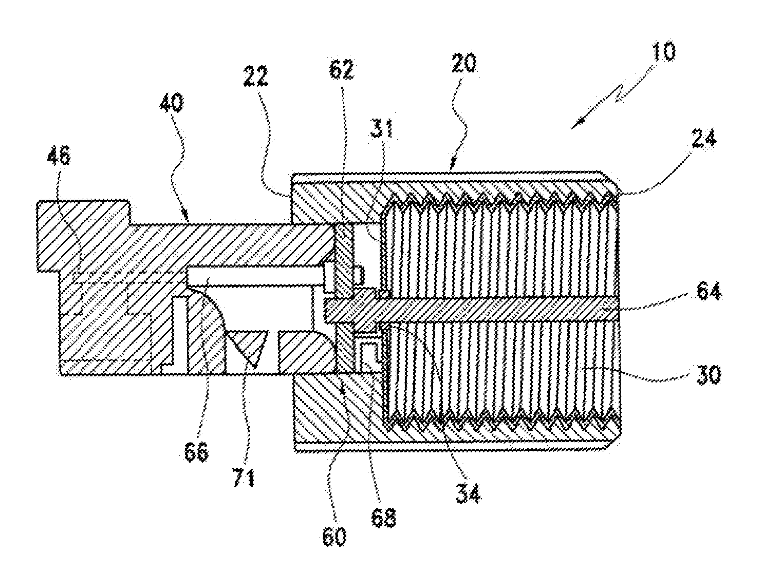
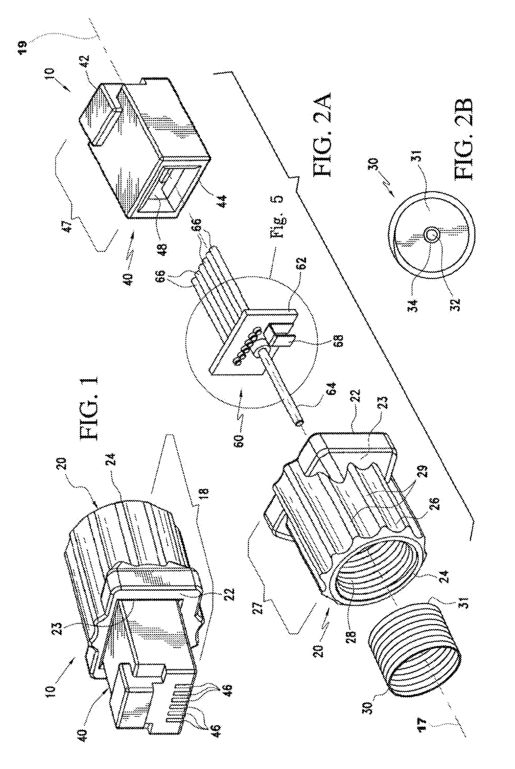
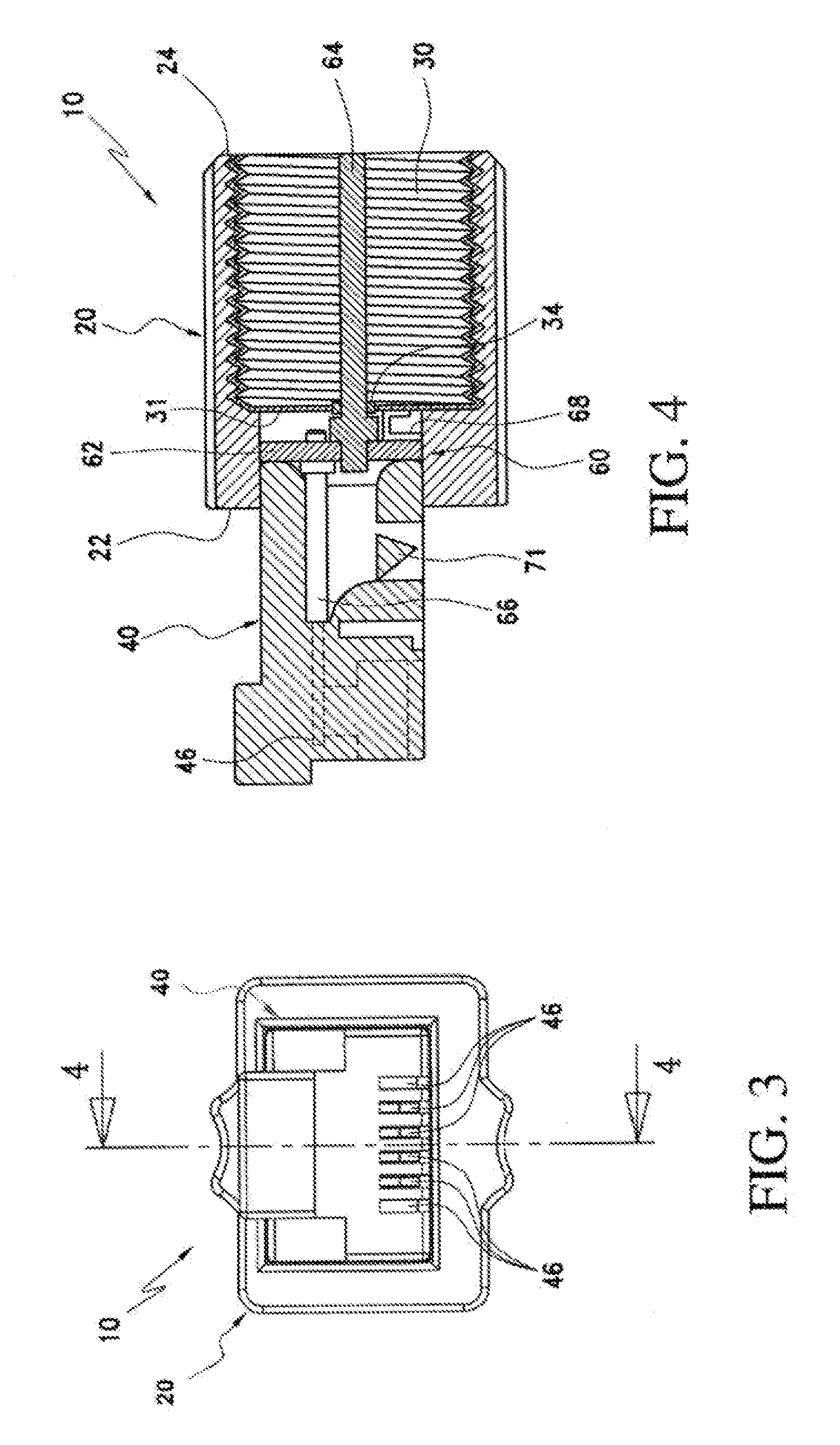
[0032]FIG. 1 is a perspective view of a device or test adapter 10, made in accordance with the invention. The device 10 is a continuity test adapter for testing the continuity in a telephone line comprising a first member 20, a second member 40 and a third member 60, as shown in FIG. 2. The first member 20 is operably configured to engage a coaxial cable female connector. The second member 40 is operably configured to engage an electrical female connector receptacle. The device 10, in the present embodiment, the first member 20 is operably configured to engage a testing device, such as the Gale Pocket Toner, U.S. Pat. No. 6,437,580, and the second member 40 is operably configured to engage an electrical female connector receptacle. In the present embodiment the electrical connector receptacle is a standard female telephone RJ-11 jack (not shown). The second member 40 engages the female RJ-11 jack to permit a user to test a telephone line in the RJ-11 jack for continuity.

[0033] As s...


PUM


Abstract

An electrical continuity tester adaptor for attaching to a conventional continuity tester comprising first, second and third members. The first member is operably configured to engage a female F-type connector. The second member is operably configured to engage a female RJ series type connector. The third member includes a plurality of electrical connections and a printed circuit board to facilitate the electrical connectivity between the first and second members.

Description

CROSS REFERENCE TO RELATED APPLICATION [0001] This nonprovisional application claims the benefit of Provisional Application No. 60 / 691,150, filed on Jun. 15, 2005, which is incorporated herein by reference in its entirety and to which priority is claimed.BACKGROUND OF THE INVENTION [0002] 1. Field of Invention [0003] The present invention relates generally to electrical circuit tester adapters for testing and tracing electrical circuit; and, it relates more specifically to adapters for testing the continuity of telephone and local area network (LAN) cables. [0004] 2. Description of Related Art [0005] Wire connectivity is essential to the proper function of telephone systems; cable television (CATV) systems; security systems; closed-circuit television (CCTV) systems; local and wide area computer networks (LANs and WANs); and, other multi-node, and multi-user systems. When a wire fault is encountered, the tracing of individual cables through wire bundles, and confirming their electric...

Claims


Application Information

Patent Timeline
Patent Type & Authority Applications(United States)
IPC IPC(8): G01R31/26
CPCG01R1/0416G01R31/026H01R24/62H01R31/06H01R2103/00H01R24/542G01R31/54
Inventor GALE, ROBERT D.
Owner GALE ROBERT D
Learn More