
Power supply apparatus

Active Publication Date: 2006-12-21
SONY CORP
View PDF3 Cites 15 Cited by
  • Summary
  • Abstract
  • Description
  • Claims
  • Application Information

AI Technical Summary

Benefits of technology

[0019] In view of the above, it is desirable not to be damaged by rush current, and it is desirable to improve power loss; to reduce capacity imbalance among respective series-connected-battery blocks; and to improve discharge time, when a plurality of series-connected-battery blocks are connected in parallel.
[0021] In the power supply device according to an embodiment of the present invention, the constant-current control circuit is provided for each of the series-connected-battery blocks. When the series-connected-battery blocks with potential differences are connected in parallel, rush current may flow into the series-connected-battery block with a low potential difference from the series-connected-battery block with a high potential difference. However, since each constant-current control circuit prevents a fixed current or more from flowing into each of the series-connected-battery blocks, the series-connected-battery block of a low potential difference is prevented from being damaged.
[0023] That is, according to an embodiment of the present invention, capacity balance among respective series-connected-battery blocks is improved, and so discharge time is extended and safety is improved by improving the capacity balance among the series-connected-battery blocks.
[0024] Further, according to an embodiment of this invention, power loss at the time of discharge can be improved, with a FET (Field-effect Transistor) for example, which functions as a current control element constituting the constant-current control circuit, being “ON” state at the time of the discharge.

Problems solved by technology

When discharge current flows into a load from this power supply device of the related art, there is caused power loss of
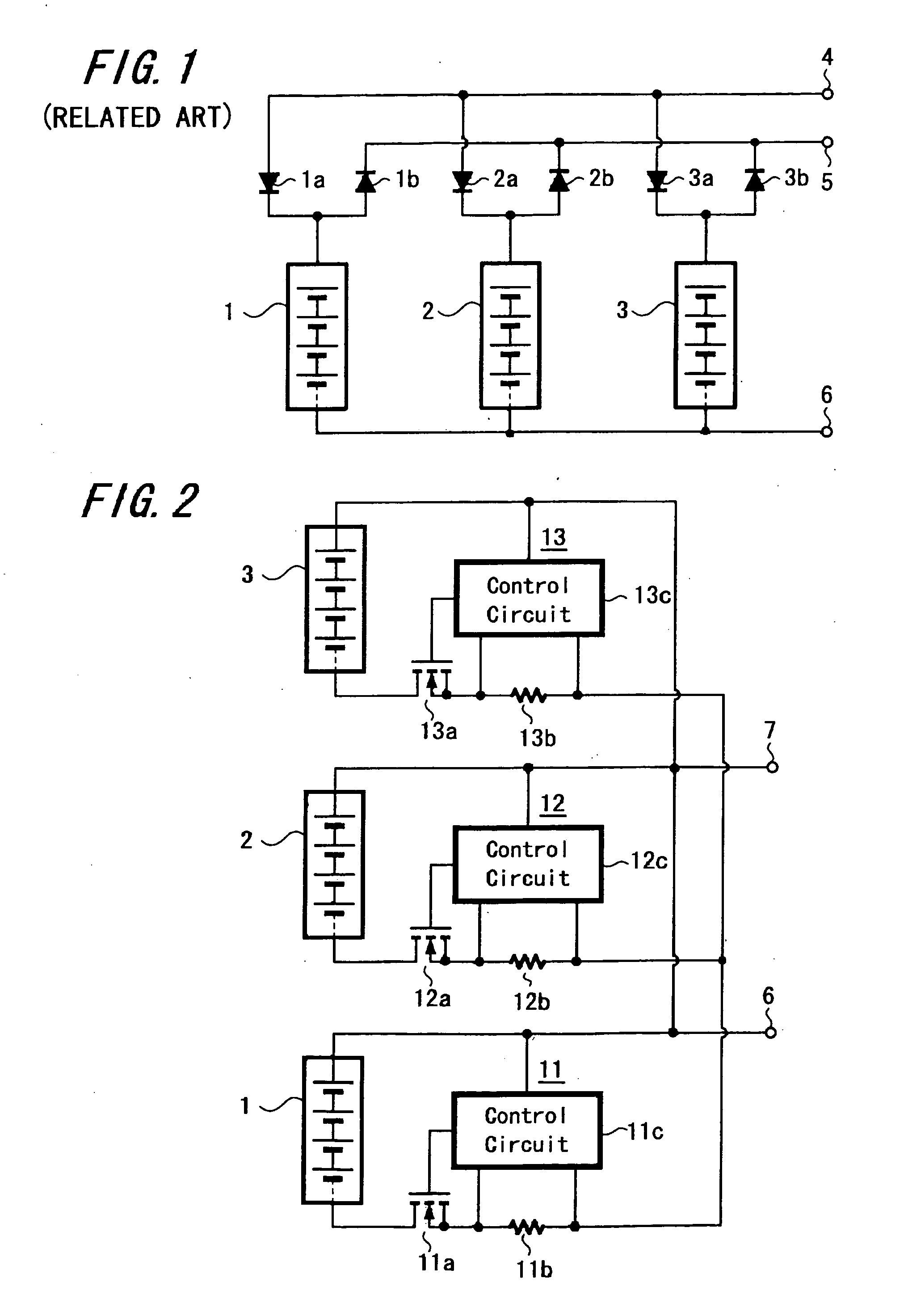
There is an inconvenience that if the current from the power supply device increases, the power loss due to the diodes 1b, 2b and 3b becomes so large that it may not be disregarded.
When the charge and discharge are performed in the state in which the capacity balance among respective series-connected-battery blocks 1, 2 and 3 is not maintained, there is such inconvenience that discharge time becomes short, or the like.

Method used


Image

  • Power supply apparatus

Examples


Embodiment Construction

[0027] Hereinafter, an embodiment of the power supply device of the present invention is explained with reference to FIG. 2. In FIG. 2, portions corresponding to those in FIG. 1 are given the same numerals and shown.

[0028] In FIG. 2, reference numerals 1, 2 and 3 each denote a series-connected-battery block in which two or more, for example four, secondary cells capable of charging and discharging, for example lithium-ion batteries, are connected in series.

[0029] In this embodiment, these three series-connected-battery blocks 1, 2 and 3 are connected in parallel, and each positive electrode of the series-connected-battery blocks 1, 2 and 3 is connected to a positive terminal 7 of the power supply device, respectively.

[0030] In this embodiment, each negative electrode of the series-connected-battery blocks 1, 2 and 3 is connected to each drain of n-type FETs 11a, 12a and 13a functioning as current control elements that constitute constant-current control circuits 11, 12 and 13, re...


PUM


Abstract

A power supply device having a plurality of series-connected-battery blocks which are connected in parallel and in which two or more secondary cells capable of charging and discharging are connected in series, includes a constant-current control circuit provided for each of the series-connected-battery blocks.

Description

CROSS REFERENCES TO RELATED APPLICATIONS [0001] The present invention contains subject matter related to Japanese Patent Application JP 2005-166976 filed in the Japanese Patent Office on Jun. 9, 2005, the entire contents of which being incorporated herein by reference. BACKGROUND OF THE INVENTION [0002] 1. Field of the Invention [0003] The present invention relates to a power supply device of comparatively large capacity that includes a plurality of series-connected-battery blocks which are connected in parallel and in each of which two or more secondary cells capable of charging and discharging are connected in series. [0004] 2. Description of the Related Art [0005] There has been proposed a power supply device of comparatively large capacity that includes a plurality of series-connected-battery blocks which are connected in parallel and in each of which two or more secondary cells capable of charging and discharging are connected in series. In such power supply device, when connec...

Claims


Application Information

Patent Timeline
IPC IPC(8): H02J7/00
CPCH02J7/0022H02J7/0013
Inventor TAKAHASHI, TSUKASA
Owner SONY CORP
Learn More