
Structure for connecting terminal parts of electrodes of plasma display panel and plasma display panel having the same

Inactive Publication Date: 2006-12-21
SAMSUNG SDI CO LTD
View PDF3 Cites 12 Cited by
  • Summary
  • Abstract
  • Description
  • Claims
  • Application Information

AI Technical Summary

Benefits of technology

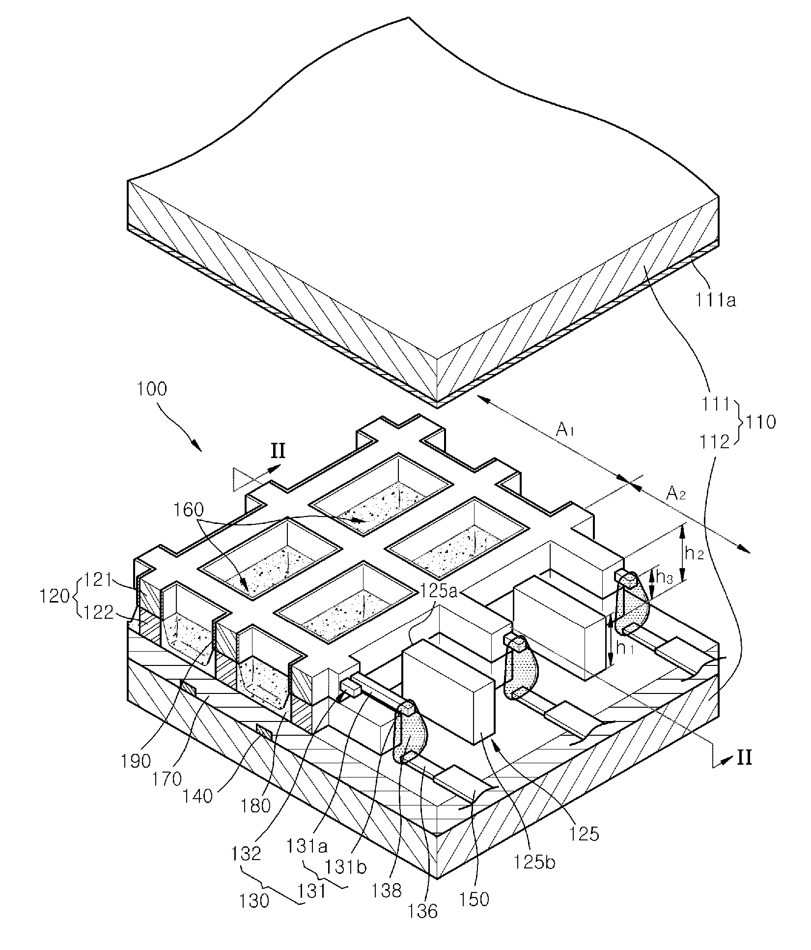
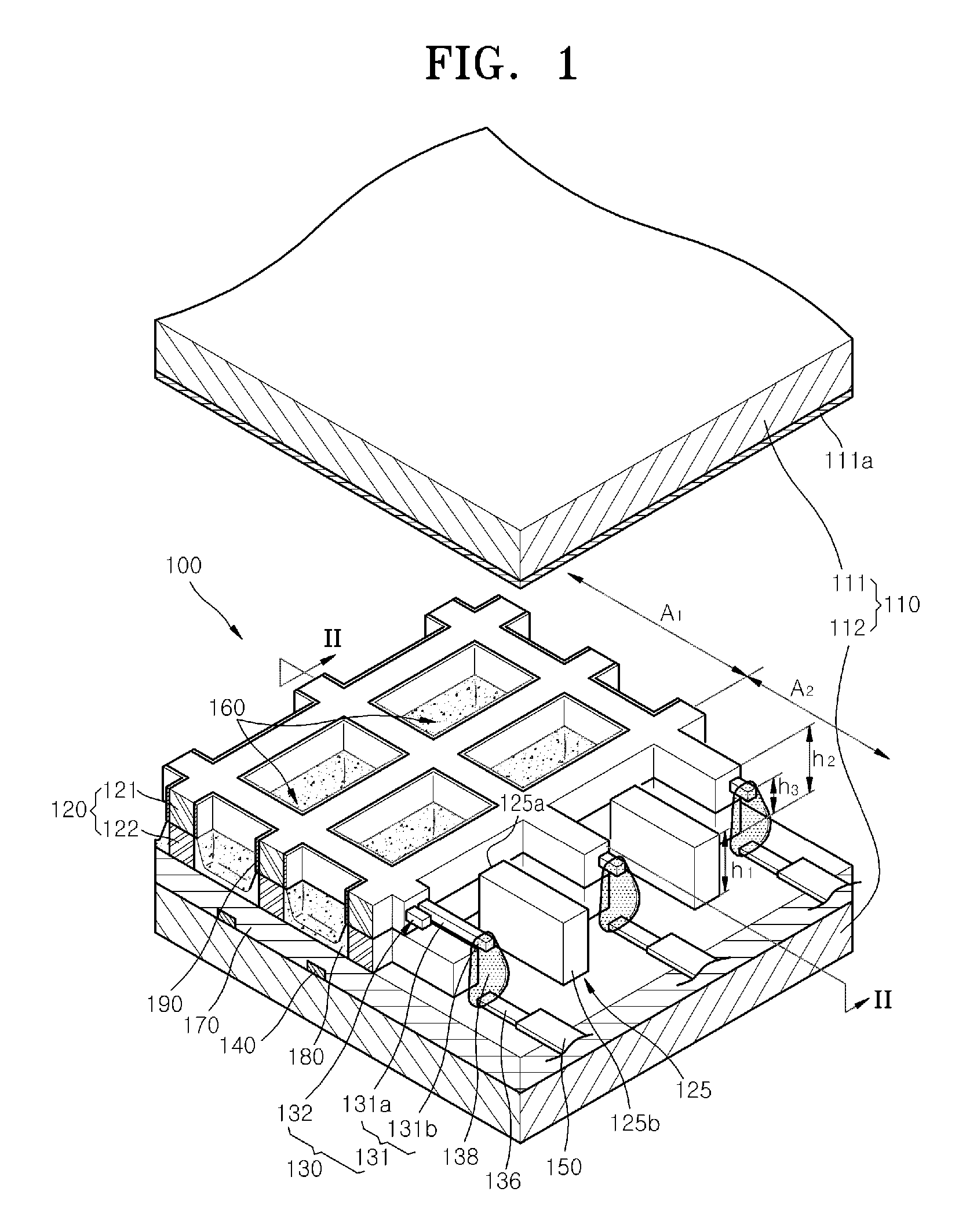
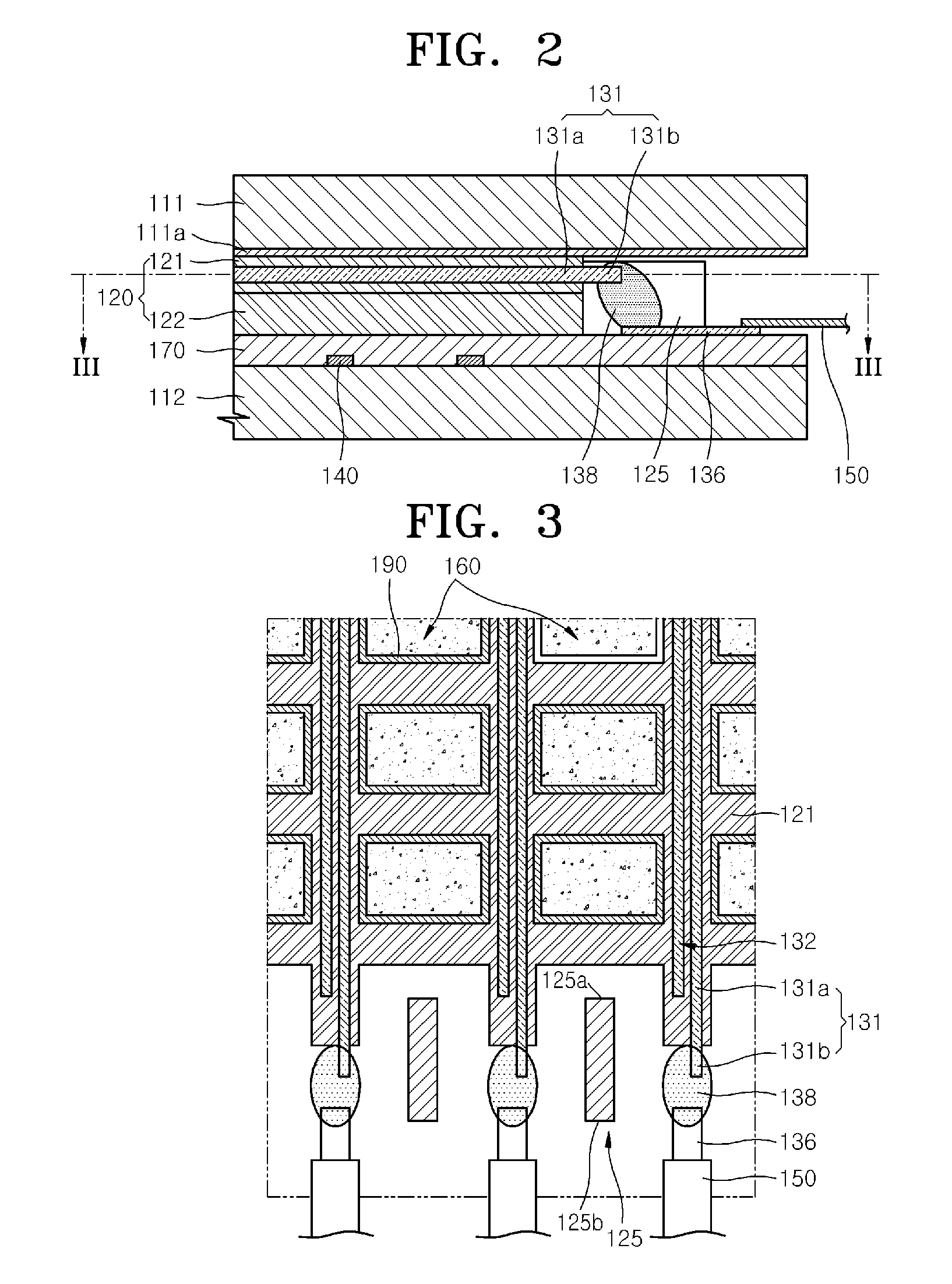
[0009] The present invention provides a structure for connecting terminal parts of electrodes of a plasma display panel (PDP), by which discharge electrodes and terminal electrodes may be more reliably and efficiently connected with each other using connection parts made of conductive paste and blocking partition walls, and a PDP having the same.

Problems solved by technology

Thus, when electrically connecting the ends of the discharge electrodes and the terminal electrodes to each other, the ends of the discharge electrodes may be damaged, or the discharge electrodes may be shorted together.

Method used


Image

  • Structure for connecting terminal parts of electrodes of plasma display panel and plasma display panel having the same
  • Structure for connecting terminal parts of electrodes of plasma display panel and plasma display panel having the same
  • Structure for connecting terminal parts of electrodes of plasma display panel and plasma display panel having the same

Examples


first embodiment

[0028] Furthermore, while the first embodiment has a structure in which visible rays generated by phosphor layers 180 are emitted through the first substrate 111, visible rays may be emitted through the second substrate 112 by forming the second substrate 112 of a transparent material such as glass.

[0029] The barrier ribs 120 include a first barrier rib 121 and a second barrier rib 122.

[0030] The first barrier rib 121 and the second barrier rib 122 define a plurality of discharge cells 160 together with the first substrate 111 and the second substrate 112.

[0031] While the barrier ribs 120 are shown divided into the first barrier ribs 121 and the second barrier ribs 122, the barrier ribs 120 may be one body.

[0032] Since the first substrate 111 and the second substrate 112 are longer than the barrier ribs 120, they may sufficiently define the discharge cells 160 together with the barrier ribs 120 and still allow the signal transmitting members 150 to be easily located in areas betw...

second embodiment

[0115] The barrier ribs 220, the blocking partition walls 225, the sustain electrode pairs 230, the terminal electrodes 236, and the connection parts 238 of the PDP 200 are configured described above. The individual conductive lines forming the signal transmitting members 250 are respectively electrically connected with the terminal electrodes 236.

[0116] After assembling the PDP 200 and adding discharge gas, address discharge occurs when applying an address voltage between the common electrodes 231 and the scan electrodes 232 from an outside power source, thereby selecting discharge cells 260 in which sustain discharge will occur.

[0117] If a discharge sustain voltage is applied between the common electrodes 231 and the scan electrodes 232 of the selected discharge cells 260 via the signal transmitting members 250, sustain discharge occurs due to a movement of wall charges accumulated on the common electrodes 231 and the scan electrodes 232, and the energy level of the discharge ga...


PUM


Abstract

A structure for connecting terminal parts of electrodes of a plasma display panel (PDP) includes a pair of substrates, barrier ribs arranged between the pair of substrates, a dielectric layer arranged between the pair of substrates, discharge electrodes, each having a discharge part arranged inside the barrier ribs, and an exposed part arranged at an end of the discharge part and outside the barrier ribs, terminal electrodes arranged on the dielectric layer, connection parts including conductive paste electrically connecting the exposed parts with the terminal electrodes, blocking partition walls arranged between the connection parts, and signal transmitting members electrically connected with the terminal electrodes.

Description

CROSS-REFERENCE TO RELATED APPLICATION [0001] This application claims priority to and the benefit of Korean Patent Application No. 10-2005-0052020, filed on Jun. 16, 2005, which is hereby incorporated by reference for all purposes as if fully set forth herein. BACKGROUND OF THE INVENTION [0002] 1. Field of the Invention [0003] The present invention relates to a structure for connecting terminal parts of electrodes of a plasma display panel (PDP), and a PDP having the same, and more particularly, to a structure for connecting terminal parts of electrodes of a PDP, by which discharge electrodes and terminal electrodes may be reliably connected with each other, and a PDP having the same. [0004] 2. Discussion of the Background [0005] Plasma display panels (PDPs) are widely considered to be the best replacement for conventional cathode ray tube (CRT) display devices. Generally, a plasma display device contains a discharge gas sealed between two substrates having a plurality of electrodes...

Claims


Application Information

Patent Timeline
IPC IPC(8): H01J17/49H01J11/12H01J11/14H01J11/16H01J11/22H01J11/24H01J11/26H01J11/32H01J11/34H01J11/46H01J11/48
CPCH01J11/46H01J11/16H01J11/22H01J11/34
Inventor KWON, JAE-IKKANG, KYOUNG-DOOYI, WON-JUWOO, SEOK-GYUN
Owner SAMSUNG SDI CO LTD
Learn More