
Compact coin denomination discriminating device

Active Publication Date: 2006-12-14
ASAHI SEIKO CO LTD
View PDF11 Cites 14 Cited by
  • Summary
  • Abstract
  • Description
  • Claims
  • Application Information

AI Technical Summary

Benefits of technology

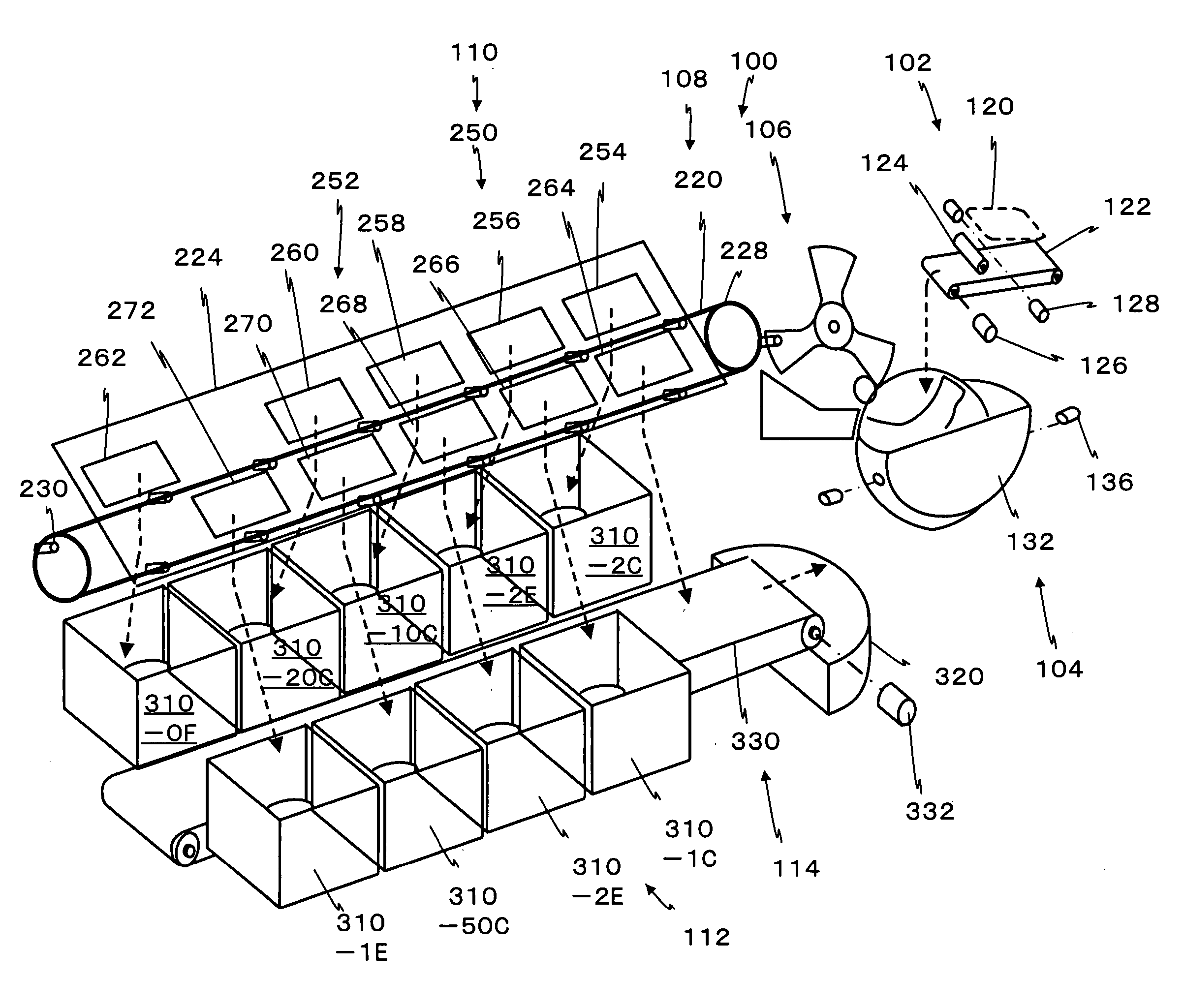
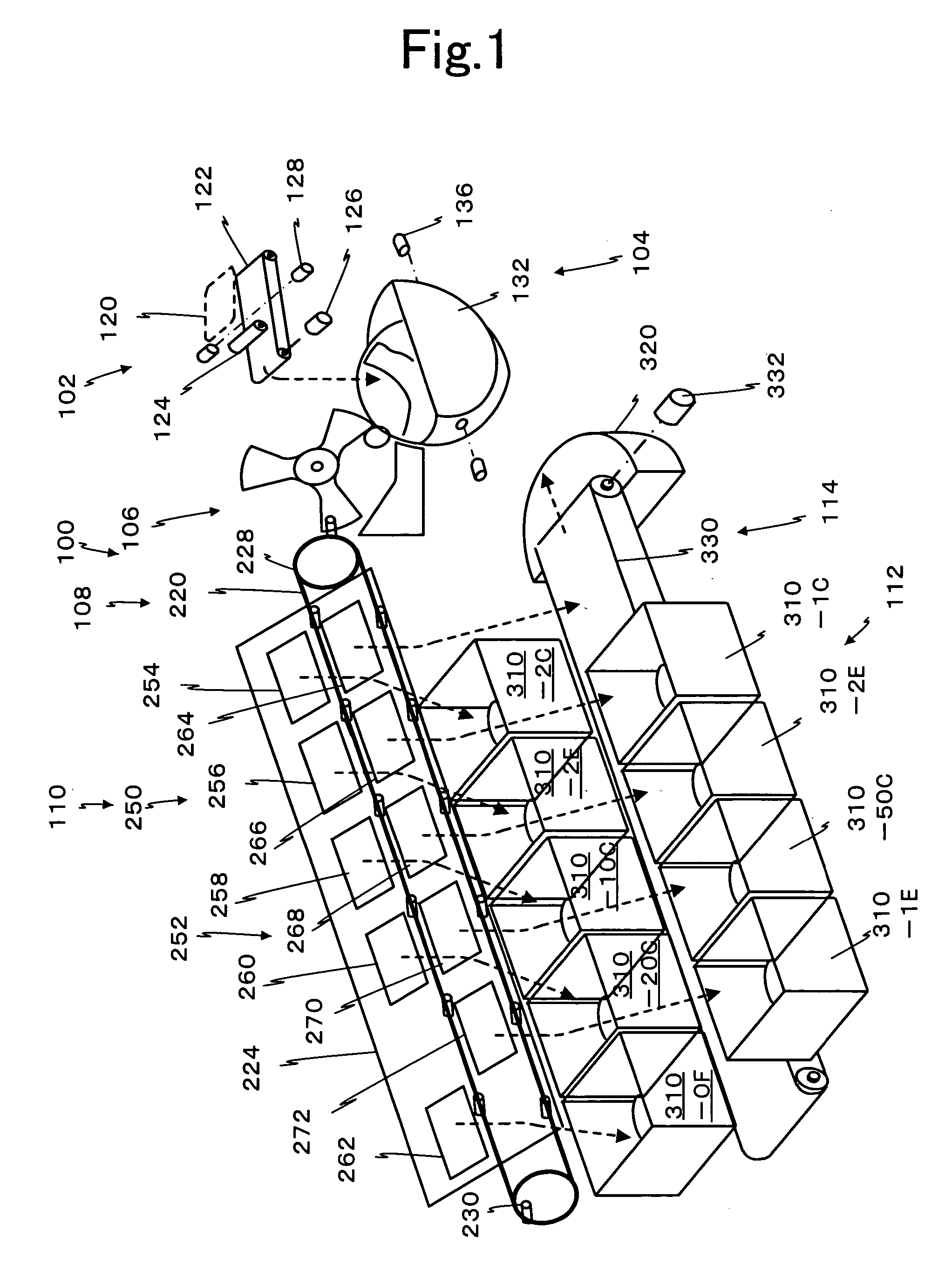
[0013] It is a first object of the present invention to provide a coin denomination discriminating device capable of realizing a high discrimination accuracy when a plural of different denominations of coins are subjected to denomination discrimination during conveyance.
[0014] It is a second object of the present invention to provide a coin denomination discriminating device for realizing high discrimination accuracy and also suited for use in a miniaturized coin receiving apparatus.

Problems solved by technology

In Japanese Patent No. 2,769,410, since the denomination of a coin is discriminated only by a diameter measurement acquired from a coin diameter detector, there is a measurement problem that the accuracy in the discrimination of a specific denomination may be poor.
Since the discrimination of the coin relies only on the diameter, coins of the same diameter would be discriminated as real coins regardless of the material or thickness, and determined as a denomination corresponding to that diameter, so that there arises a problem that fake coins cannot be discriminated.
Since a metal chain is used as coin conveying means, if a magnetic sensor that is commonly used for discriminating coin denomination is used, the magnetic sensor could be influenced by the metal chain, so that accurate discrimination cannot be achieved.
In Japanese Patent No. 3,198,288, if the processing speed of coin discrimination is increased, a medal may leave a reference plane due to centrifugation force because the medal is elastically pushed toward the rotary center from the circumference by a wiper, which may interfere with an accurate detection.
In addition, when coins of different diameters are inserted, accuracy of diameter detection cab be poor because the guiding portion of medal must be arcuate.
In other words, erroneous discrimination may occur when a plural denominations of coins having different diameters are attempted to be discriminated.

Method used


Image

  • Compact coin denomination discriminating device
  • Compact coin denomination discriminating device
  • Compact coin denomination discriminating device

Examples


Embodiment Construction

[0036] Reference will now be made in detail to the preferred embodiments of the invention which set forth the best modes contemplated to carry out the invention, examples of which are illustrated in the accompanying drawings. While the invention will be described in conjunction with the preferred embodiments, it will be understood that they are not intended to limit the invention to these embodiments. On the contrary, the invention is intended to cover alternatives, modifications and equivalents, which may be included within the spirit and scope of the invention as defined by the appended claims. Furthermore, in the following detailed description of the present invention, numerous specific details are set forth in order to provide a thorough understanding of the present invention. However, it will be obvious to one of ordinary skill in the art that the present invention may be practiced without these specific details. In other instances, well known methods, procedures, components, a...


PUM


Abstract

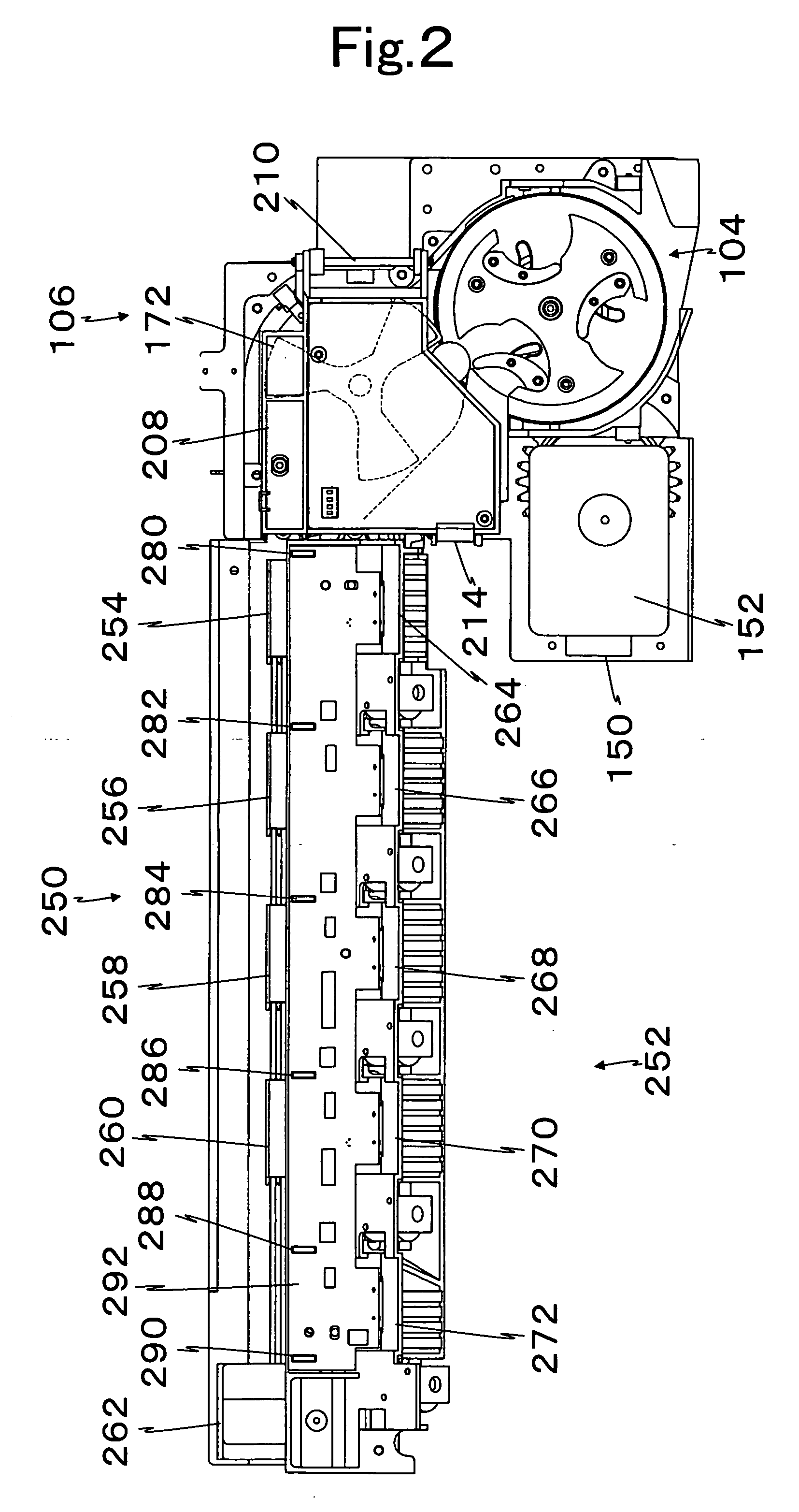
A coin denomination discriminating device for improving coin dispensing devices which incorporates components formed of non-magnetic material including a non-magnetic rotor having a coin receiving portion and a non-magnetic reference guide to guide coins from a storage coin holding bowl to a coin conveying device capable of selectively releasing coins of various denominations. Magnetic sensor units can be positioned along the coin movement path to provide characteristic signals representative of the coins independent of influence of metallic components in the transporting path. The non-magnetic members can be formed from wear resistant plastic material and relatively inexpensive magnetic sensors with coil and ferrite coils can be utilized adjacent the rotor.

Description

BACKGROUND OF THE INVENTION [0001] 1. Field of the Invention [0002] The present invention relates to a compact coin denomination discriminating device which can discriminate the denominations of a plurality of coins that are received in bulk, based on the diameter, material and thickness of the coins. The present invention also relates to a coin recycling machine which holds received coins of different denominations in holders according to denomination, and dispenses a specified number of coins in response to an instruction from a related machine. [0003] 2. Description of Related Art [0004] The term “coin” used herein embraces currency coins, medallions, tokens and medals, which may be circular or polygon in shape. [0005] In Japanese Patent No. 2,769,410, coins are sent one by one to a coin conveyance path when latched by a pin projecting from a turn table that turns within a hopper. Coin denomination is discriminated based on a diameter acquired by a coin diameter detecting unit du...

Claims


Application Information

Patent Timeline
IPC IPC(8): G07D5/08
CPCG07D3/10G07D3/128G07D5/08G07D5/02G07D3/14
Inventor UMEDA, MASAYOSHIENOMOTO, MINORUOTOMO, HIROSHI
Owner ASAHI SEIKO CO LTD
Learn More