
Record medium with a load distribution program recorded thereon, load distribution method, and load distribution apparatus

a load distribution and load technology, applied in the field of record mediums with load distribution programs recorded thereon, load distribution methods, load distribution apparatus, can solve the problems of delay in providing services, especially difficult to estimate a resource quantity required in the future, and achieve high quality

Inactive Publication Date: 2006-11-30
FUJITSU LTD
View PDF7 Cites 60 Cited by
  • Summary
  • Abstract
  • Description
  • Claims
  • Application Information

AI Technical Summary

Benefits of technology

[0022] The present invention was made under the background circumstances described above. An object of the present invention is to provide a record medium on which a load distribution program capable of dynam...

Problems solved by technology

With the rapid spread of the Internet in recent years, however, it has become difficult to estimate a resource quantity required in the future.
In such a case, it is especially difficult to estimate a resource quantity required.
If there is an error in estimating the quantity requested per unit time, then there are delays in providing services at the time of a flood of requests.
However, if other conditions are not considered, service quality mismatching may occur among service classes.
Actually, there may be factors, such as a resource quantity which can be secured in each center and uneven distribution of users, so it is difficult to allocate each client to the most suitable center.
Moreover, even if each client can be allocated to the most suitable center, there is often waste in the use of resources.
However, if servers are allocated according to processing layers in an on-demand environment, delay between the processing layers must also be taken into consideration.

Method used


Image

  • Record medium with a load distribution program recorded thereon, load distribution method, and load distribution apparatus
  • Record medium with a load distribution program recorded thereon, load distribution method, and load distribution apparatus
  • Record medium with a load distribution program recorded thereon, load distribution method, and load distribution apparatus

Examples


Embodiment Construction

[0051] An embodiment of the present invention will now be described with reference to the drawings.

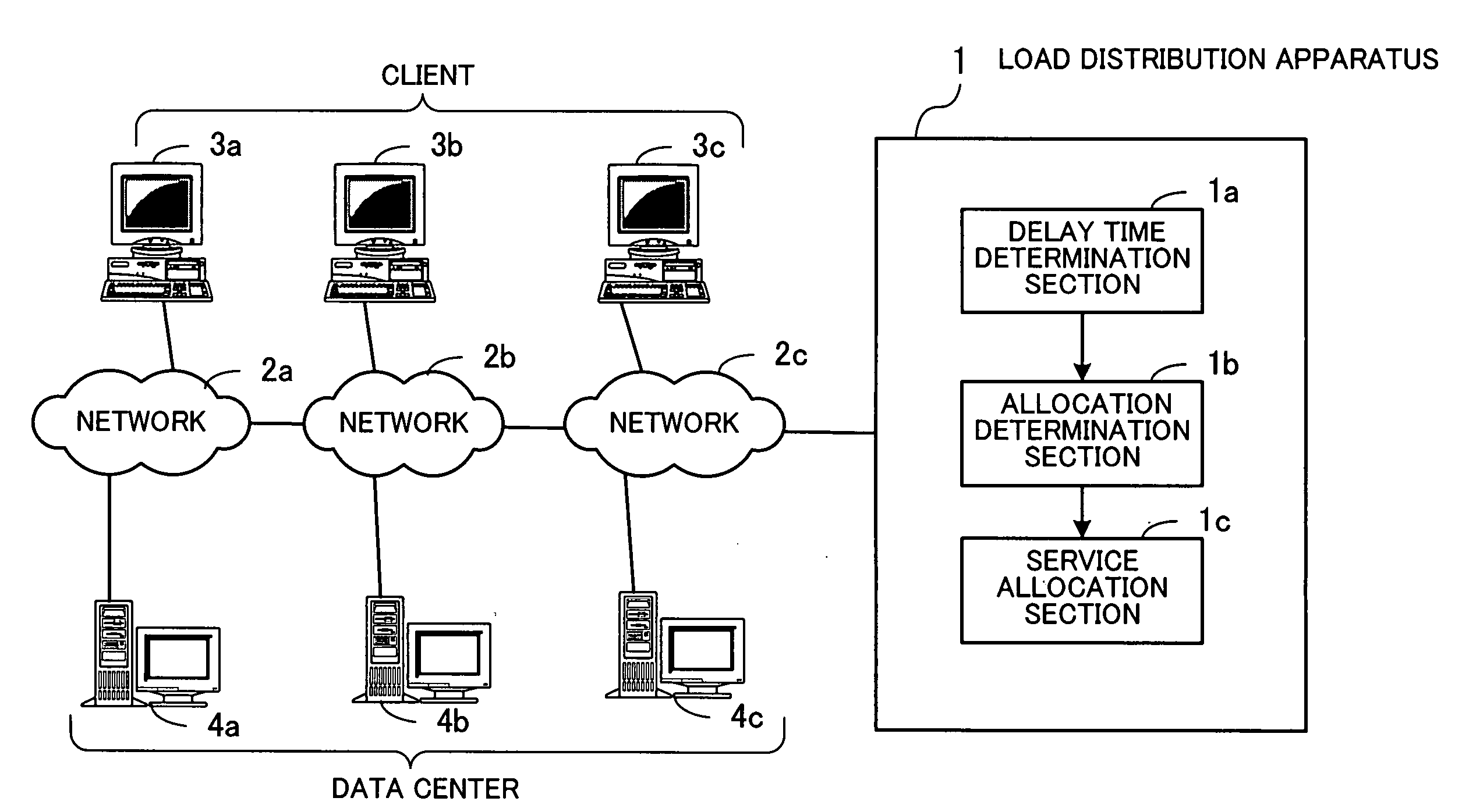
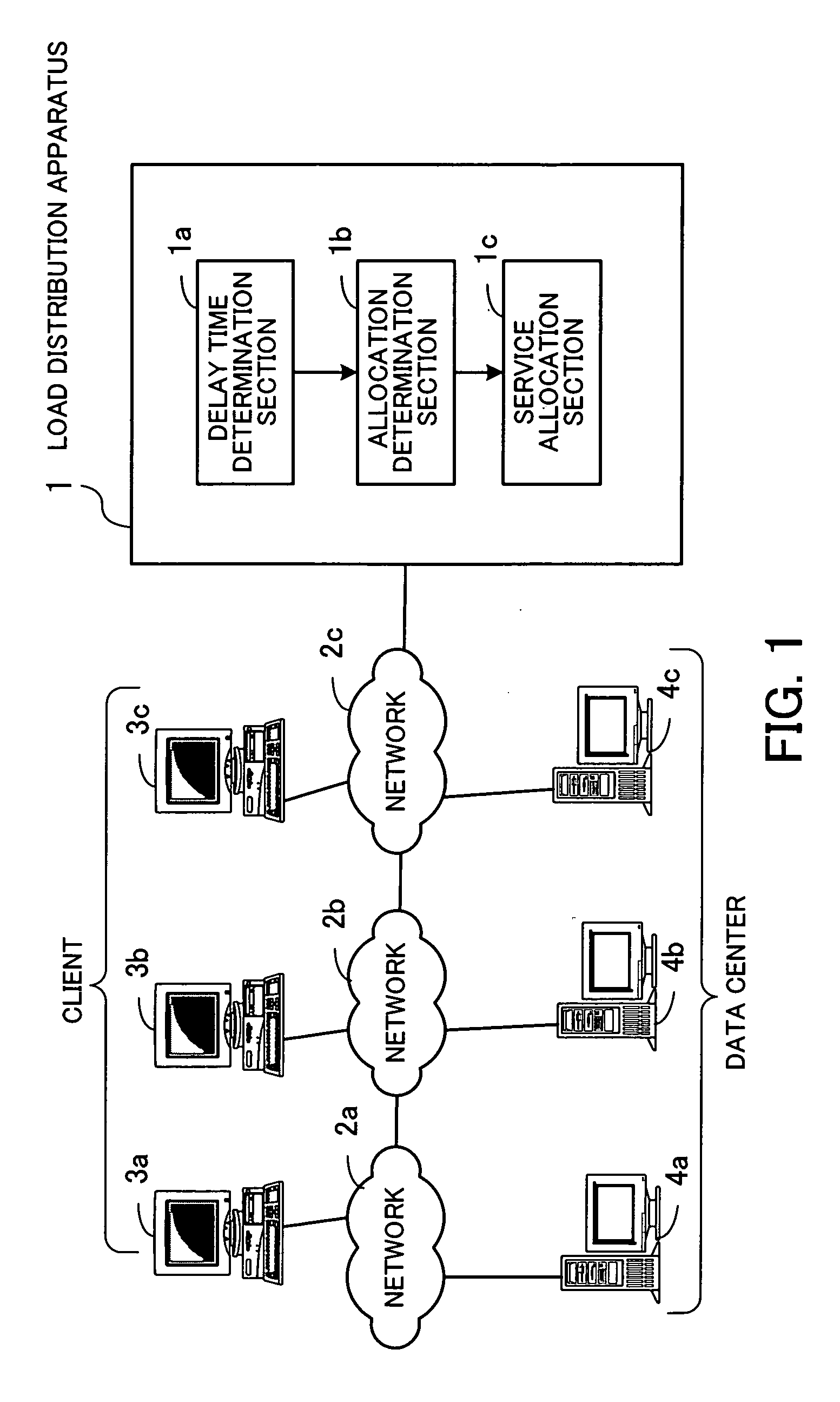
[0052]FIG. 1 is a view for giving an overview of an embodiment of the present invention. As shown in FIG. 1, a load distribution apparatus 1 is connected to clients 3a through 3c and data centers 4a through 4c via networks 2a through 2c. Each of the data centers 4a through 4c has one or more servers by which it provides predetermined services to the clients 3a through 3c. To dynamically allocate requests from the clients 3a through 3c to the data centers 4a through 4c, the load distribution apparatus 1 includes a delay time determination section 1a, an allocation determination section 1b, and a service allocation section 1c.

[0053] The delay time determination section 1a analyzes a request sent from a client and identifies a position on the network 2a, 2b, or 2c of the client. For example, the delay time determination section 1a specifies a server for Internet access services to which...


PUM


Abstract

A record medium on which a load distribution program capable of dynamically determining a service providing server which can provide a service of high quality according to a place where a client is installed is recorded. A delay time determination section analyzes a request sent from a client, identifies a position on a network of the client, and determines processing delay time the client takes to receive a response from each data center on the basis of a communication path between the position of the client and a position on the network of each data center. An allocation determination section preferentially selects a data center which can provide a service to the client after shortest processing delay time as a recommended data center on the basis of the processing delay time determined by the delay time determination section. A service allocation section makes a server in the recommended data center provide the service to the client which outputted the request.

Description

CROSS-REFERENCE TO RELATED APPLICATIONS [0001] This application is based upon and claims the benefits of priority from the prior Japanese Patent Application No. 2005-150418, filed on May 24, 2005, the entire contents of which are incorporated herein by reference. BACKGROUND OF THE INVENTION [0002] (1) Field of the Invention [0003] This invention relates to a record medium on which a load distribution program for distributing a processing load on each of a plurality of servers is recorded, a load distribution method, and a load distribution apparatus and, more particularly, to a record medium on which a load distribution program for dynamically determining a server for performing a process each time a process request is received from a client is recorded, a load distribution method, and a load distribution apparatus. [0004] (2) Description of the Related Art [0005] In ordinary client server systems, the quantity requested by clients are estimated in advance and resources, such as ser...

Claims


Application Information

Patent Timeline
IPC IPC(8): G06F15/16H04L12/803H04L12/701
CPCH04L67/1008H04L67/2814H04L67/1002H04L67/1021H04L67/101H04L67/1001H04L67/563
Inventor KAWAI, TSUTOMUSEKIGUCHI, ATSUJITSUCHIYA, SATOSHISHIMOJIMA, KAZUKI
Owner FUJITSU LTD
Learn More