
Method and apparatus for manufacturing internally coated glass tubes

a technology of glass tubes and inner surfaces, which is applied in the direction of glass making apparatus, glass shaping apparatus, nanotechnology, etc., can solve the problems of many limitations, glass types are often not able to meet the required specifications, and the manufacture of such glasses is often relatively expensive, so as to achieve rapid faster and complete particle reaction, and large oxygen content

Inactive Publication Date: 2006-11-23
SCHOTT AG
View PDF17 Cites 67 Cited by
  • Summary
  • Abstract
  • Description
  • Claims
  • Application Information

AI Technical Summary

Benefits of technology

[0015] It is an object of the present invention to provide a method and a device with which internally coated glass tubes can be manufactured easily and economically. A further aspect of the present invention concerns the use of an internally coated glass tube made by this method for further processing into a hollow, internally coated formed glass body.
[0017] According to the invention, the substance is introduced or dumped as a dispersion and the inner surface is coated by the substance or a decomposition or reaction product during the hot forming. According to the invention, the dispersion may be present in the form of a suspension or as an aerosol, that is, in the form of finely dispersed solid particles in a liquid or a gas. Also conceivable is use of a suspension. In any event, the substance has a large surface area when introduced and this favours and accelerates reactions with the hot inner surface during hot forming, for example chemical reactions, or deposition, as will be described in greater detail below. According to the invention, the very finely dispersed state of the liquid or solid particles also enables even coating of the whole inner surface of the glass tube. A further advantage is that the method according to the invention can be carried out continuously or semi-continuously, so that the glass tube can be drawn off continuously or semi-continuously.
[0020] According to a further embodiment of the present invention, the dispersion is introduced or dumped into the softened glass bag at a predetermined excess pressure. The relatively high flow rate of the aerosol, of the suspension or of the emulsion thereby achievable makes it possible, for example, for the respective substance to be rapidly introduced or dumped into the region of hot forming, that is at a temperature below the critical temperature above which the substance undergoes thermal decomposition, reacts, precipitates or the like.
[0023] According to a further embodiment, an aerosol is formed in a process gas which is blown into the bag of softened glass. This process gas may be, in particular, CO2, noble gases or mixtures thereof, to which oxygen can also be added in a suitable concentration. However, the process gas can in principle also have a larger oxygen content compared to the atmosphere, even to the extent of being pure oxygen, which can be advantageous for the further reaction of the aerosol particles in the hot forming process.
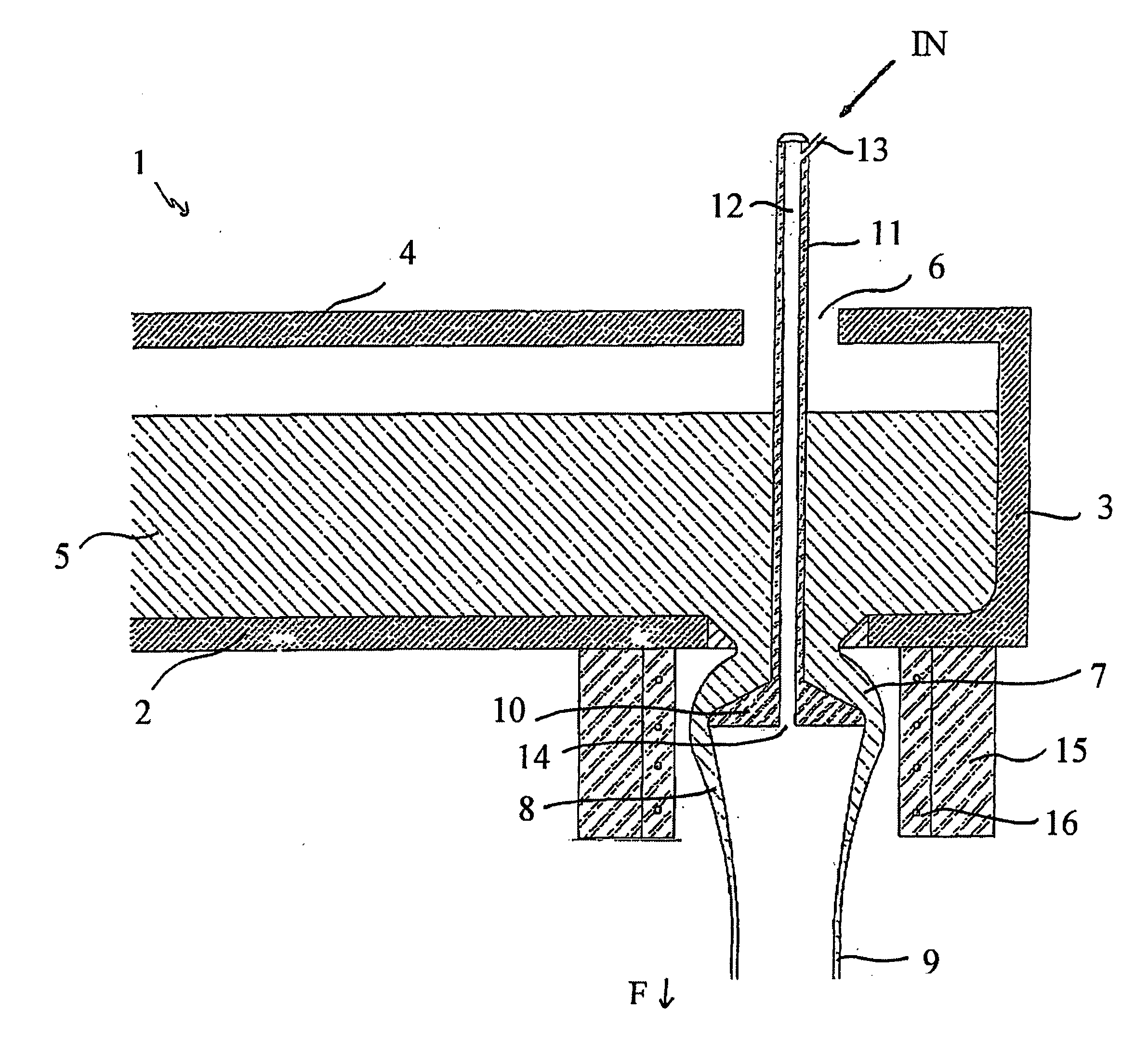
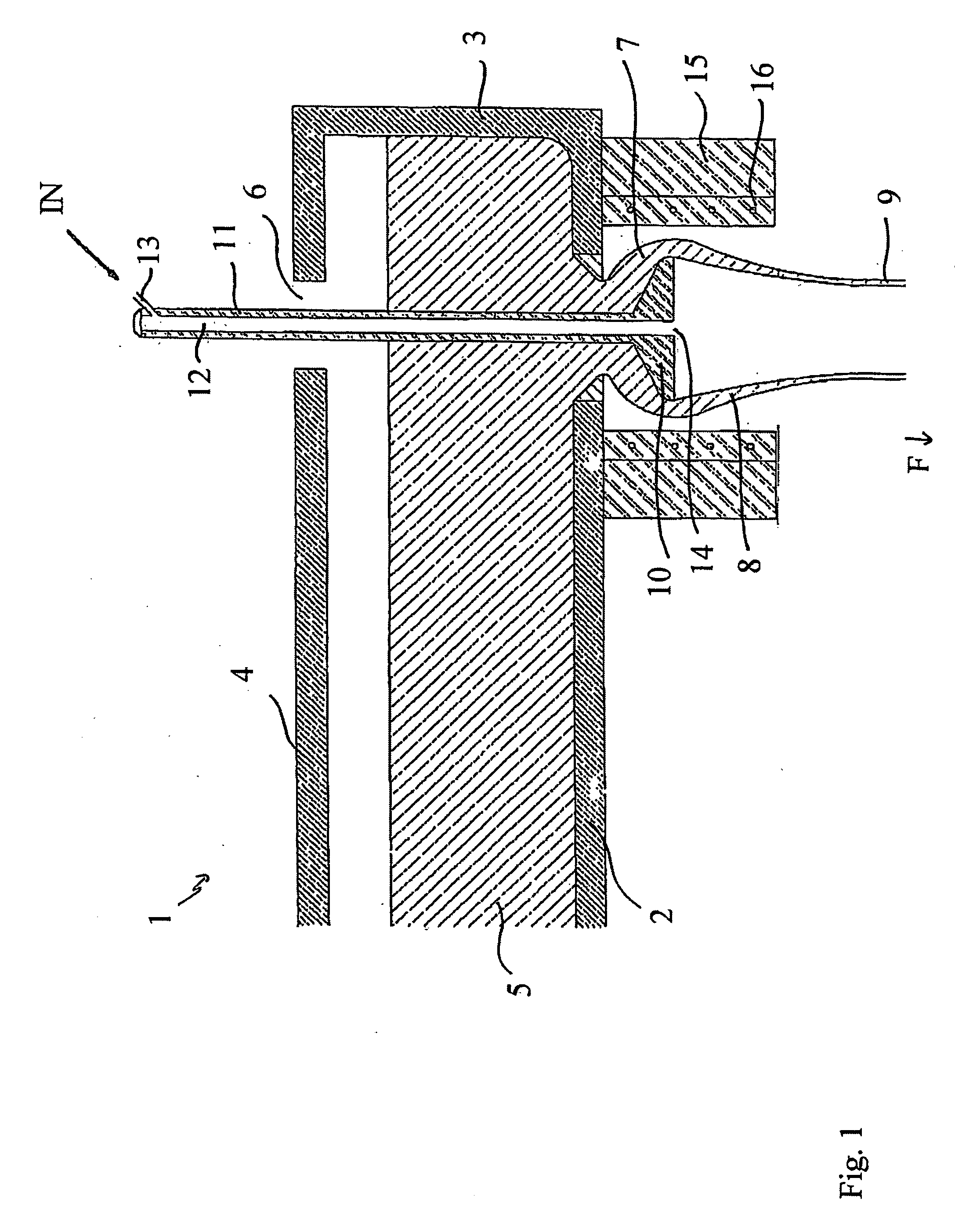
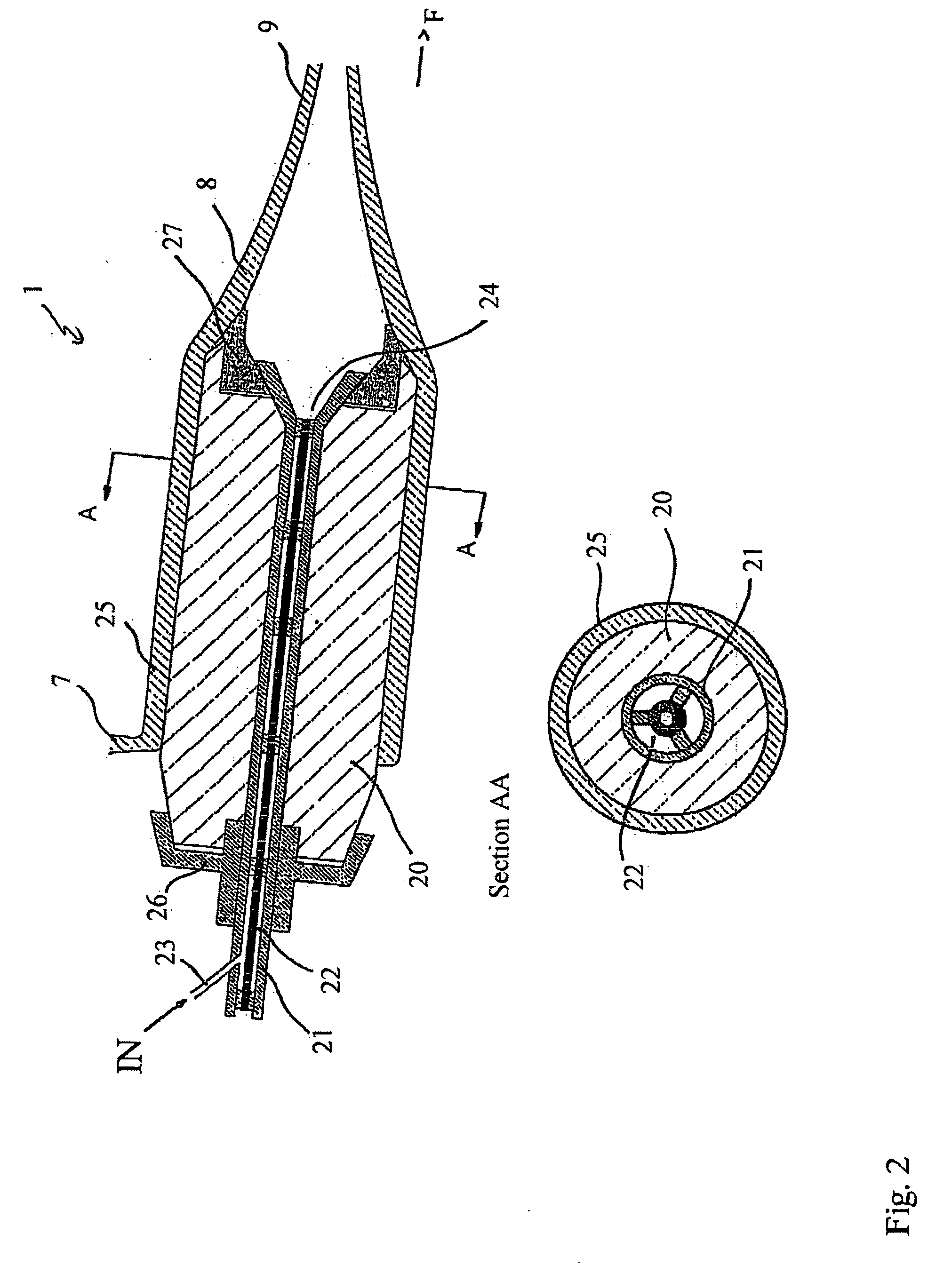
[0024] According to a further embodiment, an aerosol is introduced through an outlet opening at the front end of a forming body, over which the glass melt is drawn. For this purpose, the forming body suitably has an axial inner bore so that the aforementioned outlet opening can communicate with an inlet for the aerosol. This inlet can be provided in a relatively cool region of the device, which enables use of simple hose or line connections for feeding in the aerosol.
[0025] According to a further embodiment, the solid or liquid particles in the aerosol, suspension or emulsion have an average diameter of less than approximately 5 μm. The resulting large surface area of the aerosol enables, for example, rapid and complete reaction of the particles for internal coating. Still faster and more complete reaction of the particles is achieved if the average diameter of the aerosol particles is less than approximately 3 μm. A yet more complete and rapid reaction of the particles is achieved with an average particle diameter of less than approximately 1 μM.

Problems solved by technology

However, the manufacturing of such glasses is frequently relatively expensive.
Furthermore, such glass types are often not able to comply with the required specifications, particularly with regard to their formability into hollow bodies at the lowest possible temperatures.
Methods of this type, however, are subject to numerous limitations.
The cost for suitable modification of the inner surface is therefore shifted onto the manufacturer of the hollow formed glass body, which is frequently undesirable for reasons of cost and suitability.
Due to the usually fundamentally different manufacturing parameters, the principles applied to discontinuous manufacturing methods cannot be transferred to continuous manufacturing methods, or cannot be transferred without further effort, so that they do not offer any inspiration to persons skilled in the art for improving continuous or semi-continuous manufacturing methods.
The chemicals used are relatively aggressive.
This is unacceptable for many technical applications, particularly in the pharmaceutical industry.
With this method, also, aggressive substances have to be used, and this is undesirable for the reasons given above.
However, the coating on the drawing die becomes used up in the course of time, resulting in stoppages while the die is changed, which are time-consuming and costly.
This method is not suitable for continuous manufacturing of internally coated glass tubes.
Due to the fundamentally different geometrical conditions and process parameters, the principles applied to this different technical field are not transferable, or not without difficulty, to the internal coating of glass tubes in a continuous glass drawing process, so that they do not offer any inspiration to persons skilled in the art for improving such processes.

Method used


Image

  • Method and apparatus for manufacturing internally coated glass tubes
  • Method and apparatus for manufacturing internally coated glass tubes
  • Method and apparatus for manufacturing internally coated glass tubes

Examples


exemplary embodiment 1

[0043] In this exemplary embodiment, a glass tube made of Fiolax was internally coated. The tube was drawn at a drawing speed of 0.733 metres per second and a throughput rate of 670 kg per hour to an outer diameter of 30.0 mm and a wall thickness of 1.20 mm. The cutting length of the glass tubes was 158 cm. The hydrolytic resistance was ascertained with a test to RS-TA 2010, as described below. Furthermore, the internal coating of the glass tube was tested by means of SIMS analysis (secondary ion mass spectroscopy) to a depth of approximately 160 nm. There was no substantial change in the glass composition. The layer thicknesses achieved were in the range of 50 nm to 100 nm.

[0044] The aerosols were formed from finely ground or nanoscale powders of organometallic compounds or metal oxides. Any metals could be used with the exception of the alkali metals. The organometallic compounds included, in particular, the citrates, tartrates and lactates. The metal oxides that were investigate...


PUM

PropertyMeasurementUnit
Fractionaaaaaaaaaa
Fractionaaaaaaaaaa
Fractionaaaaaaaaaa

Abstract

The invention relates to a method for manufacturing a glass tube with a coated inner surface by drawing a glass melt (5) to a bag (8) of softened glass and hot forming to a glass tube (9). During the process a substance is introduced into the bag (8) of softened glass. According to the invention the substance is introduced as an aerosol and the inner surface is coated by means of the substance during the hot forming. The method permits economical internal coating with a continuous glass drawing method. The use of aggressive chemical substances for internal coating can be dispensed with according to the invention. As a result, for example, internally coated glass tubes with improved hydrolytic resistance can be manufactured. The invention also relates to a suitable apparatus for manufacturing internally coated glass tubes and the use of glass tubes manufactured by this means for further processing to a hollow, internally coated formed glass body, for example, as primary packaging in the pharmaceuticals field.

Description

FIELD OF THE INVENTION [0001] The present invention relates in general to the manufacturing of glass tubes having an internally coated inner surface, particularly a chemically or physically modified inner surface, by means of a continuous or semi-continuous glass drawing method. The present invention also relates to the use of such glass tubes as semi-finished products for manufacturing hollow formed glass bodies by further forming the semi-finished product into hollow formed glass bodies. BACKGROUND OF THE INVENTION [0002] Technical applications for glass, for example as a starting material for primary packaging materials in the pharmaceuticals industry, increasingly demand hollow formed glass bodies whose inner surface is as chemically inert as possible in that, for example, it releases as few ions as possible into a substance stored within it or reacts as little as possible with a substance stored in the formed glass body. Glasses with inert surfaces can be prepared by suitable c...

Claims


Application Information

Patent Timeline
IPC IPC(8): C03C17/00C03B15/14C03B17/04C03B15/18C03C17/245
CPCC03B17/04C03C17/004C03C17/2456C03C17/245C03C17/22C03B17/00B82Y30/00
Inventor DICK, ERHARDFISCHER, ERICHFUCHS, ROLANDHUMMER, ALEXANDERTRATZKY, STEPHAN
Owner SCHOTT AG
Learn More