
Near-infrared absorbing film, and process for production the same, near-infrared absorbing film roll, process for producing the same and near-infrared absorbing filter

a technology film, applied in the field of near-infrared ray absorption film, can solve the problems of insufficient satisfactory, remarkable defects, and lack of uniformity of application

Inactive Publication Date: 2006-11-16
TOYO TOYOBO CO LTD
View PDF28 Cites 56 Cited by
  • Summary
  • Abstract
  • Description
  • Claims
  • Application Information

AI Technical Summary

Benefits of technology

[0016] The near-infrared ray absorption film of the present invention is a near-infrared ray absorption film in which a near-infrared ray absorption layer comprising a composition containing a near-infrared ray absorbing dye having maximum absorption in a range of 800 nm in wavelength to 1200 nm in wavelength, and further containing a resin is provided on a transparent substrate film,

Problems solved by technology

For example, in recent years, attention has been focused on a plasma display as a thin-type large screen display, but since there is a problem that an electronic equipment using a near-infrared remote control causes erroneous motions due to a near-infrared ray released from a plasma display, an attempt has been made to prevent these erroneous motions by disposing the above-described near-infrared ray absorption filter in front of a plasma display.
However, in these methods, there are some methods having the ability to sufficiently cut off a near-infrared ray released from a plasma display, and has no change with time even when used for a long period of time, but they are not sufficiently satisfactory in the coated film appearance of a near-infrared ray absorption layer for a higher luminance of a plasma display in recent years, as well as for a higher-definition and a higher quality image due to Hi-Vision broadcasting.
Defects having a size of 300 μm or greater look like luminescent spots, and such defects become remarkable, when disposed in front of a plasma display.
In addition, a thin streak, a lack of application uniformity, or the like of the coated film also become remarkable in front of a display, which becomes problematic.
This is because an ultraviolet-ray is contained in light which is introduced into a near-infrared ray absorption filter from the outside in many cases, this ultraviolet-ray causes deterioration in a near-infrared ray absorbing dye, and this becomes a cause for deterioration in the near-infrared ray absorption filter with time.
In the prior art technique regarding these composite type filters by attachment, there is a problem that attachment with a sticky layer interposed increases an interface and, consequently, optical properties are deteriorated, and there still remains a problem that an attachment step is necessary and is thus economically disadvantageous.
In addition, since the total thickness of a filter becomes great, there is a problem that the workability of attachment to a subject to be attached, such as a display, becomes poor.
However, in the mode of actual use of a filter, since a transparent sticky layer is situated at a position on a display side than a near-infrared ray shutting off layer, and a ultraviolet ray is introduced from an anti-reflective layer side together with visible light, the action of absorbing an incident ultraviolet ray before irradiation at a near-infrared ray absorbing dye cannot be exhibited, from the viewpoint of a structure.
Therefore, this cannot respond to a demand for the suppression of deterioration in the near-infrared ray absorbing dye due to the incident ultraviolet ray under the current circumstances.
However, each of the above-described gazettes neither describes nor suggests a method of improving color tone variation and coated film appearance, particularly, for a long near-infrared ray absorption film.
However, in this method, color tone variation in the longitudinal direction (MD direction) of a film can be controlled to some extent, but the suppression of color tone variation in the film width direction (TD direction) is not sufficient.
In addition, it is difficult to highly decrease color tone variation for a long near-infrared ray absorption film only by control of an application amount by the rotation number of a microgravure and, further, appearance is not satisfactory.

Method used


Image

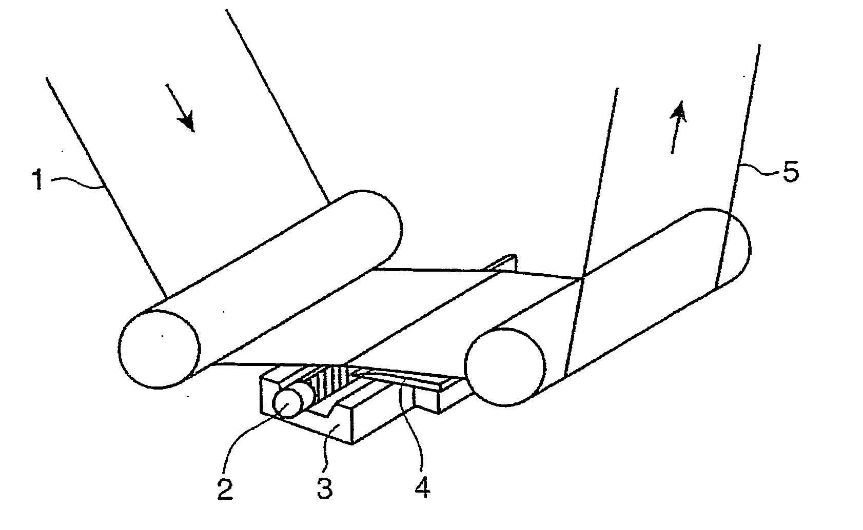
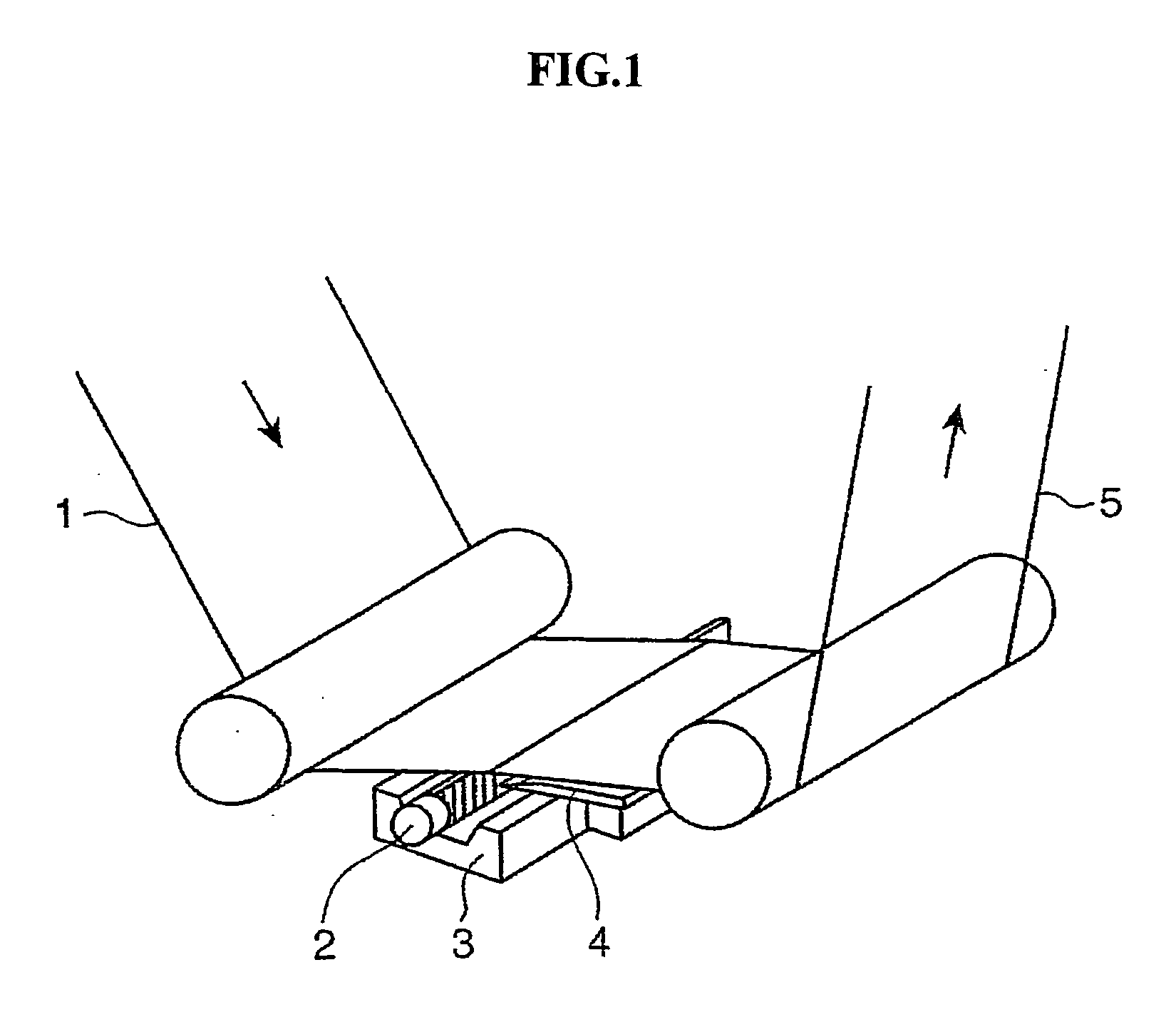
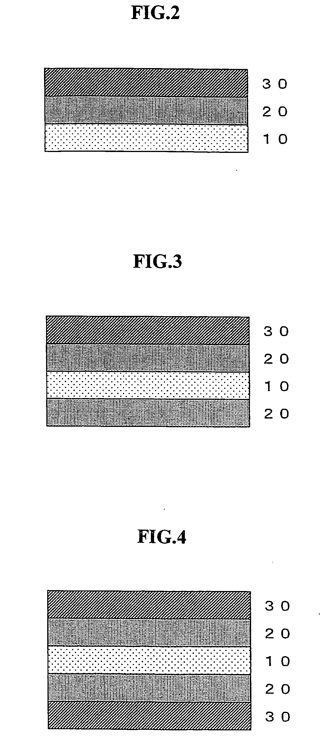
  • Near-infrared absorbing film, and process for production the same, near-infrared absorbing film roll, process for producing the same and near-infrared absorbing filter
  • Near-infrared absorbing film, and process for production the same, near-infrared absorbing film roll, process for producing the same and near-infrared absorbing filter
  • Near-infrared absorbing film, and process for production the same, near-infrared absorbing film roll, process for producing the same and near-infrared absorbing filter

Examples


experiment 1

Experiment 1-1

1. Manufacturing of Substrate Film

[0318] A polyethylene terephthalate resin having an intrinsic viscosity of 0.62 dl / g was fed to a biaxial screw extruder, melt extruded through a T-die at 290° C., and adhesion-solidified while static electricity application was imparted on a cooling rotation metal roll to obtain an unstretched sheet.

[0319] Then, the unstretched sheet was heated to 90° C. with a roll stretching machine, and longitudinally stretched at 3.5-fold, and obtained a longitudinally stretched film, a coating solution A for an intermediate layer having a composition shown in the following Table 1 was coated on both sides of the longitudinally stretched film so that a coating amount after drying became 0.5 g / m2, and this was passed for 20 seconds under the hot air at 120° C. at an air flow of 10 m / second, to form an intermediate layer. Further, this film was heated to 140° C. with a tenter, and transversely stretched at 3.7-fold, and heat-treated at 235° C. ...

experiment 1-2

[0322] According to the same manner as that of Experiment 1-1 except that the surfactant in a coating solution for forming a near-infrared ray absorption layer was changed to a silicone surfactant (FZ-2105, available from Nippon Unicar Company Limited) having HLB of 11, a near-infrared ray absorption film was obtained. Because of high hydrophilicity of the surfactant, stability with time under a high temperature and a high humidity of the film was slightly inferior. In addition, since the effect of imparting slidability due to localization on the surface was deficient, winding slippage occurred slightly. In all cases, the film was at a practical level.

experiment 1-3

[0323] According to the same manner as that of Experiment 1-1 except that the surfactant in a coating solution for forming a near-infrared ray absorption layer was changed to a silicone surfactant (FZ-2136, available from Nippon Unicar Company Limited) having HLB of 3, a near-infrared ray absorption film was obtained. Because of the high hydrophobicity of the surfactant, leveling property of the film was slightly inferior, and a small amount of a fine defect was generated.


PUM


Abstract

The near-infrared ray absorption film of the present invention is a near-infrared ray absorption film in which a near-infrared ray absorption layer comprising a composition containing a near-infrared ray absorbing dye having maximum absorption at a wavelength of 800 to 1200 nm, and a resin is provided on a transparent substrate film, and is characterized that a surfactant having HLB of 2 to 12 is contained in the composition at 0.01 to 2.0% by mass. There can be provided a near-infrared ray absorption film excellent in coated film appearance which has the wide absorbing ability in the near-infrared ray absorbing region, has a high light transmittance in the visible light region, has little change in optical properties with time, and can respond to a higher luminance of a display, and higher-definition and higher image quality by Hi-Vision broadcasting in recent years.

Description

TECHNICAL FIELD [0001] The present invention relates to a near-infrared ray absorption film and a process for its production, the film having a high transmittance in the visible light region, having little change in the transmittance with time, being uniform in coated film appearance, and being suitable for display filters; a near-infrared ray absorption film roll and a process for its production, the roll having little variation in the color tone and the like of a long film; and a near-infrared ray absorption filter using the film. BACKGROUND ART [0002] A filter having the ability to absorb a near-infrared ray has the property of cutting off a near-infrared ray and making visible light pass therethrough, and is used as a near-infrared ray absorption filter in various applications. [0003] For example, in recent years, attention has been focused on a plasma display as a thin-type large screen display, but since there is a problem that an electronic equipment using a near-infrared rem...

Claims


Application Information

Patent Timeline
IPC IPC(8): G03F1/00
CPCG03F7/2041
Inventor MORI, KENICHIYOSHIMI, AKIRAONOMICHI, SHINYASHIMIZU, TOSHIYUKIKOSAKA, TASUKUTAKI, HIROSHIMIZUNO, NAOKIIKEHATA, YOSHITOMOMORISHIGE, CHIKAO
Owner TOYO TOYOBO CO LTD
Learn More