Computer mouse

a mouse and mouse technology, applied in the field of mouse, can solve the problems of impediment to mouse operation, impaired mouse size, impaired mouse comfort, etc., and achieve the effect of hardly loosening and tangled, easy change, and improved portability

Inactive Publication Date: 2006-11-09
HOSIDEN CORP
View PDF7 Cites 7 Cited by
  • Summary
  • Abstract
  • Description
  • Claims
  • Application Information

AI Technical Summary

Benefits of technology

[0008] Preferably, an engaging concave portion or an engaging convex portion is disposed in plural peripheral places of one of the downward-concaved upper face of the mouse case and the plate-like member, and an engaging convex portion or an engaging concave portion which is fittable with the engaging concave portion or the engaging convex portion is disposed in plural peripheral places of another one of the downward-concaved upper face and the plate-like member. When this configuration is employed, the plate-like member can be attached to the downward-concaved upper face of the mouse case in both the upward-convex direction and the downward-concave direction and in a state where rattle is not caused and fixation is surely performed, and the attached

Problems solved by technology

A problem which is to be solved by the invention is that, since the portability of a conventional mouse is improved by miniaturizing or thinning the mouse, the original shape and size of the mouse which can be easily held by a hand, and which comfortably fits to the palm are impaired, and the portability cannot be improved without impairing the operability of the mouse.
In the cable treatment method in which a cable is wound around a mouse, becau

Method used


Image

  • Computer mouse
  • Computer mouse
  • Computer mouse

Examples


Embodiment Construction

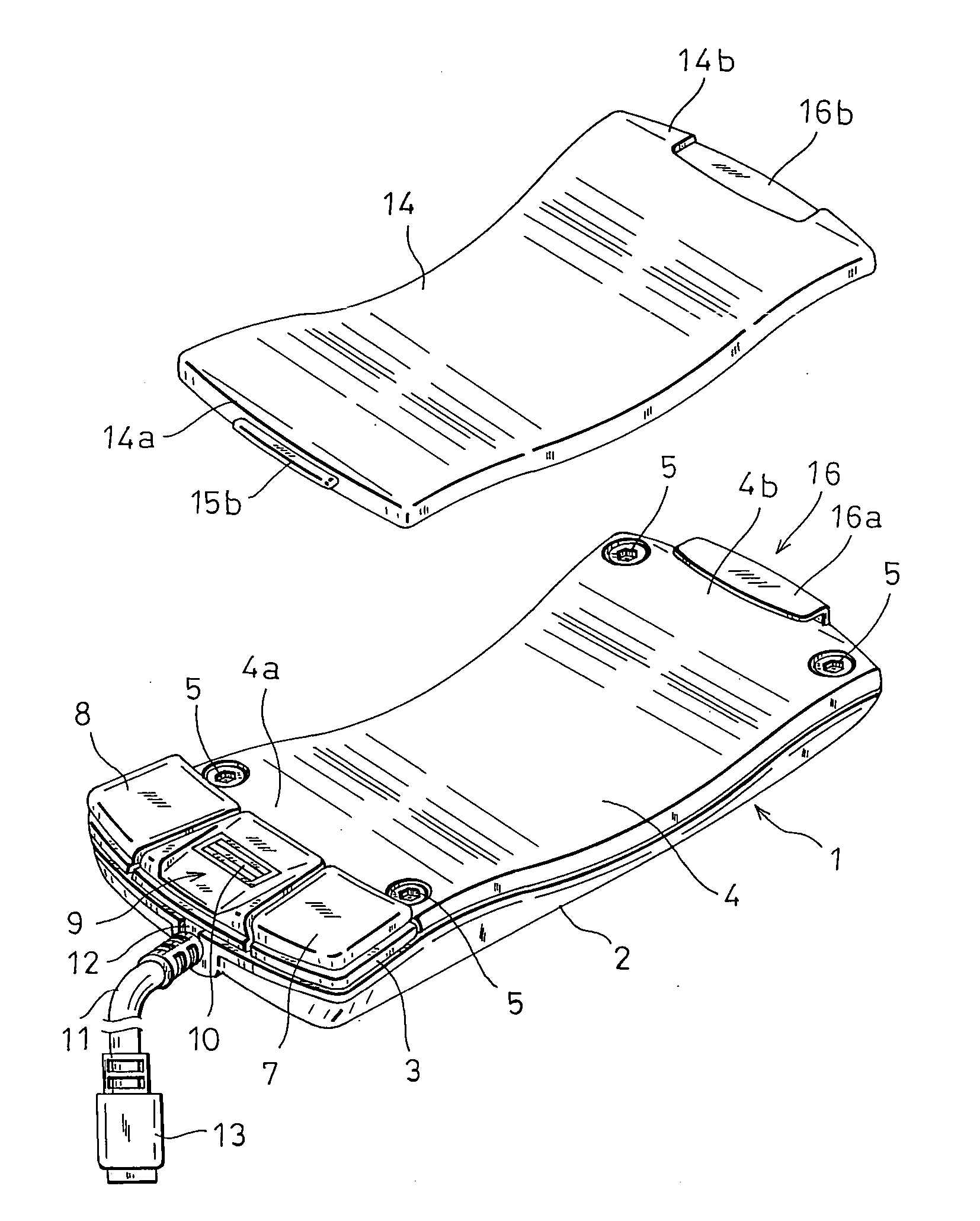
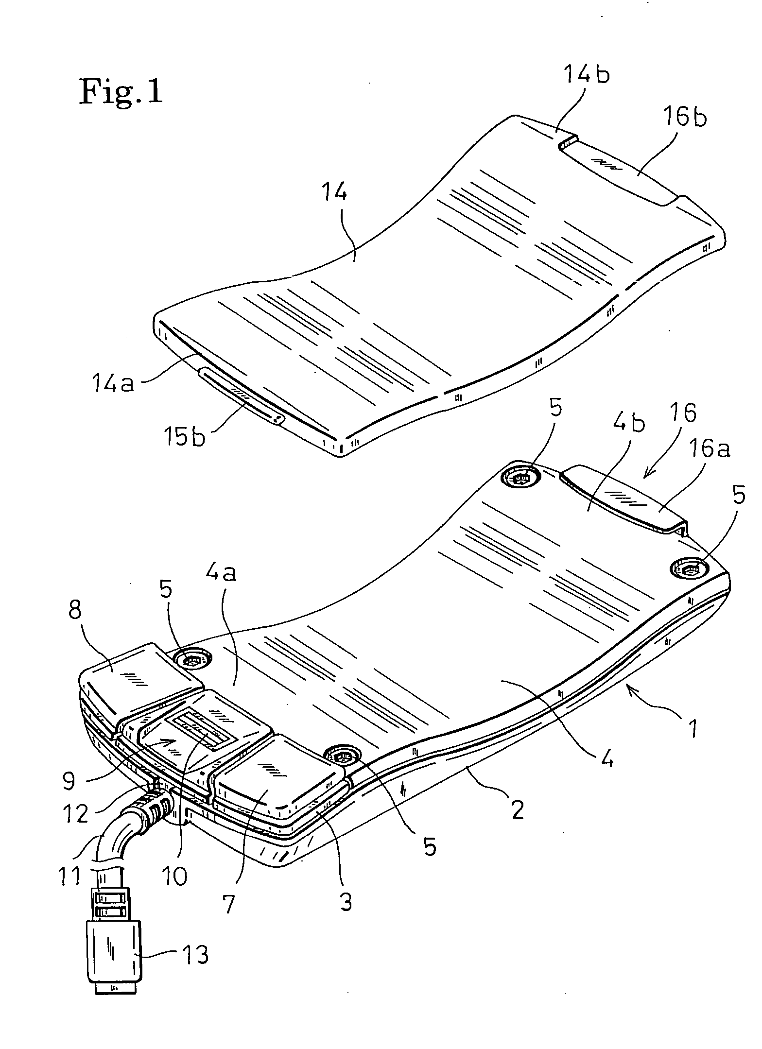
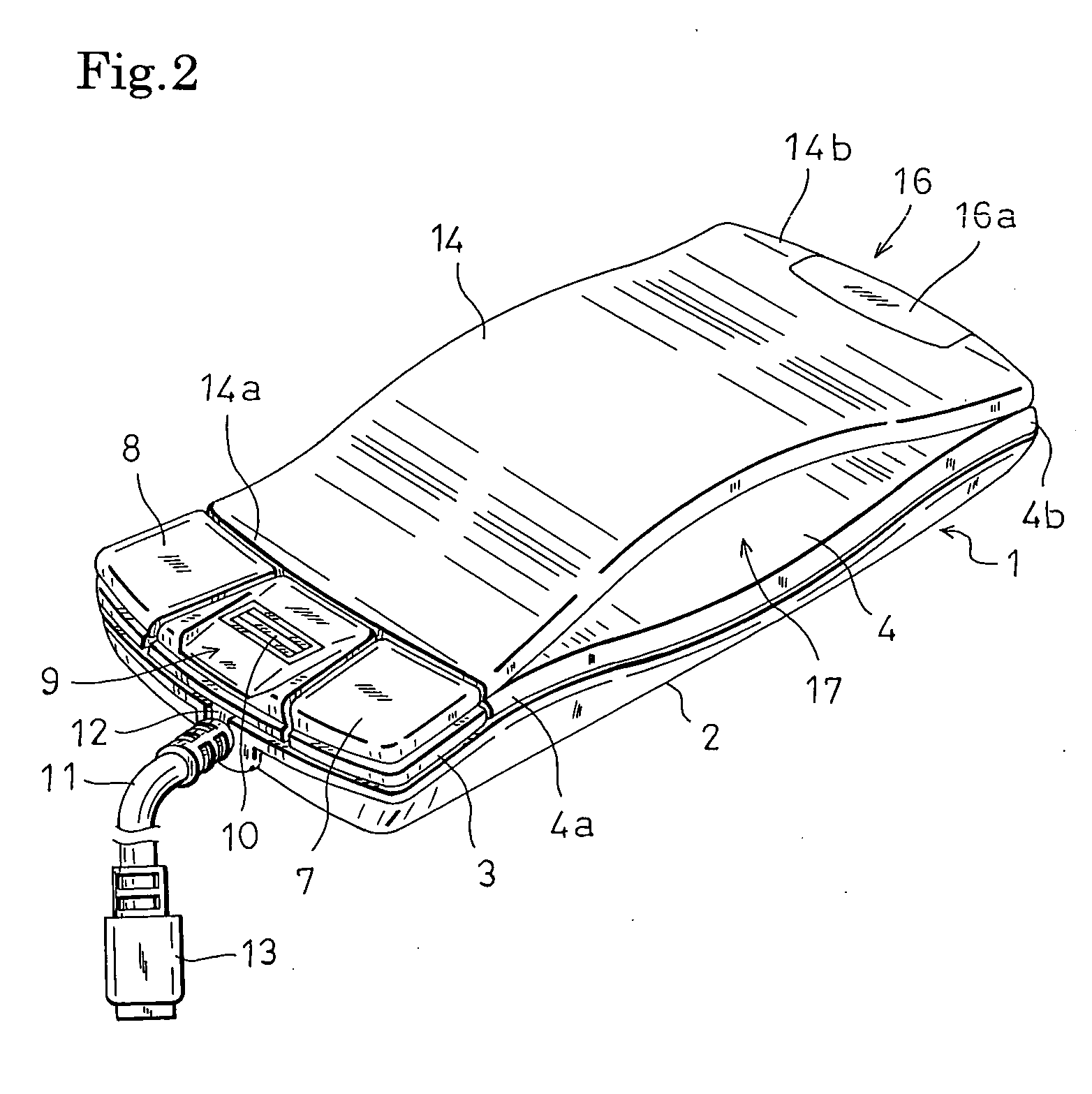
[0028] Hereinafter, an embodiment of the invention will be described with reference to the accompanying drawings. FIG. 1 is an external perspective view showing the configuration of a mouse which is the embodiment of the invention. FIG. 7 is a view showing the appearance of the mouse, FIG. 7A is a plan view of the mouse which is common in the use condition and the carry condition, FIG. 7B is a side view of the mouse in the use condition, FIG. 7C is a side view of the mouse in the carry condition, and FIG. 7D is a bottom view of the mouse which is common in the use condition and the carry condition. The embodiment will be described on the assumption that, in the case where the mouse is operated by the right hand, the fingertip side is a mouse front side, the wrist side is a mouse rear side, the thumb side is a mouse left side, and the little finger side is a mouse right side.

[0029] In FIGS. 1 and 7, 1 denotes a thin mouse case which has a substantially parallelepiped rectangular sha...


PUM


Abstract

The invention relates to a computer mouse which is one kind of coordinate input devices for a computer, and more particularly to a computer mouse which is suitably used for a portable computer. The mouse has: a thin mouse case in which an upper face portion opposing a palm when the mouse is used is formed into a downward-concaved shape; and a plate-like member having a shape which extends along the downward-concaved upper face of the mouse case, and the plate-like member is attachable to the downward-concaved upper face of the mouse case in both an upward-convex direction and a downward-concave direction. When the mouse is to be used, the plate-like member is attached in the upward-convex manner to the downward-concaved upper face of the mouse case, and, when the mouse is to be carried, the plate-like member is attached in the downward-concave manner to the downward-concaved upper face of the mouse case, thereby realizing compaction of the mouse in which the original shape and size of the mouse are reproducible.

Description

BACKGROUND OF THE INVENTION [0001] 1. Field of the Invention [0002] The present invention relates to a computer mouse (hereinafter, often referred to simply as a “mouse”) which is one kind of coordinate input devices for a computer, and more particularly to a mouse which is suitably used for a portable computer. [0003] 2. Description of the Prior Art [0004] Such a device is called a mouse because the shape and size which can be easily held by a hand, and which are designed so as to comfortably fit to the palm, and to be easily operated are similar to a house mouse. Along with the popularization of portable personal computers, a mouse is requested to be suitable for a mobile use. In order to meet the request, conventionally, small or thin mice which completely fit in a hand have been provided (for example, see Japanese Patent Application Laying-Open No. 2002-215324). Furthermore, mice which are to be connected to a computer body in accordance with the USB standard are widely used. A ...

Claims


Application Information

Patent Timeline
IPC IPC(8): G09G5/08G06F3/0354
CPCG06F3/03543G06F3/0354
Inventor SHIGENO, YASUHIROTAKEHARA, NAOYAMINE, KEIJISASADA, SOSUKE
Owner HOSIDEN CORP
Why Eureka
Try Eureka