
Method and system for controlling the improving of a program layout

a computer program and image technology, applied in the field of method and system for optimizing the working set of the program image, can solve the problems of page fault, system prone to thrashing, behavior has a very high time and computational overhead, etc., and achieve the effect of improving the working set and reducing the working s

Inactive Publication Date: 2006-11-02
MICROSOFT TECH LICENSING LLC
View PDF13 Cites 5 Cited by
  • Summary
  • Abstract
  • Description
  • Claims
  • Application Information

AI Technical Summary

Benefits of technology

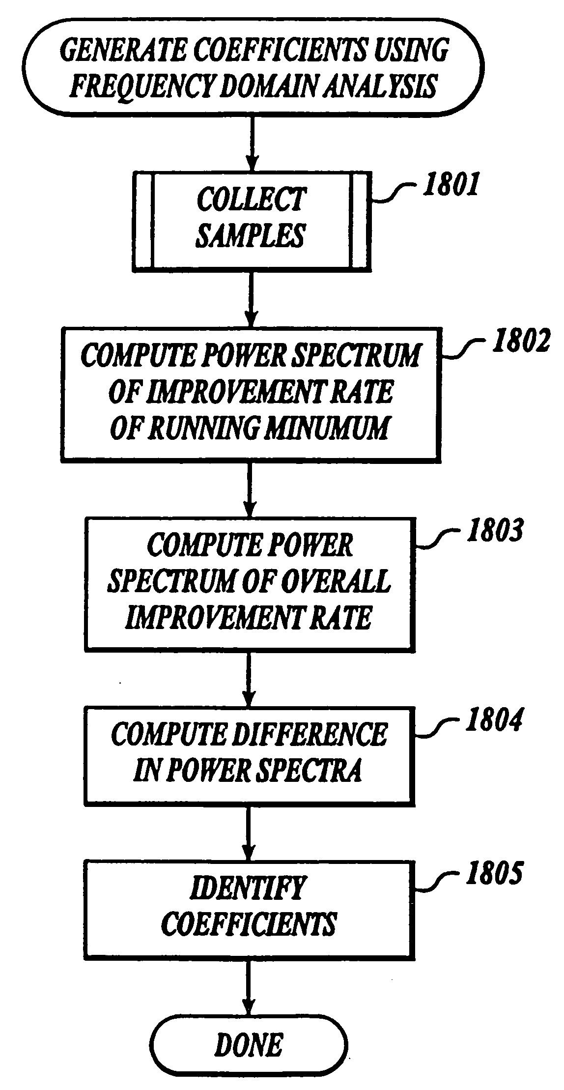
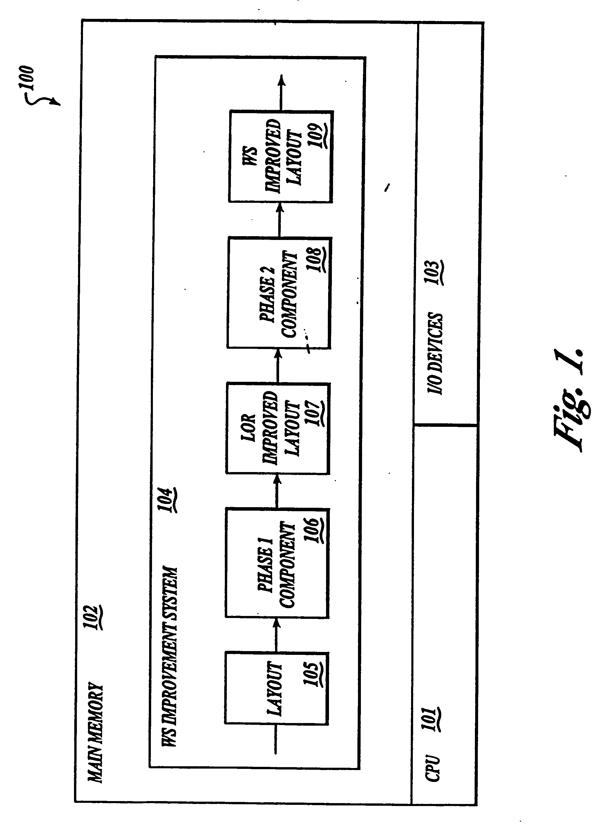
[0011] The present invention provides a method and system for improving the working set of a program image. The working set (WS) improvement system of the present invention employs a two-phase technique for improving the working set. In the first phase, the WS improvement system inputs the program image and outputs a program image with the locality of its references improved. In the second phase, the WS improvement system inputs the program image with its locality of references improved and outputs a program image with the placement of its basic blocks in relation to page boundaries improved so that the working set is reduced.

Problems solved by technology

When the computer system attempts to reference an address on a page that is not present in main memory, a page fault occurs.
If the working set is larger than the number of allocated page frames, the system will be prone to thrashing.
This behavior has a very high time and computational overhead.
Clearly this cannot be done before the executable module has been created.
To the extent that unrequired code portions are loaded into memory, valuable memory space may be wasted, and the total number of pages loaded into memory may be much larger than necessary.
Because complex program images can have thousands, and even hundreds of thousands, of code portions, such an algorithm cannot generate a minimum working set in a timely manner even when the most powerful computers are employed.
Because the use of such algorithms are impractical for all but the smallest program images, various algorithms are needed to generate a layout that results in an improved working set (albeit not necessarily the minimal working set) in a timely manner.

Method used


Image

  • Method and system for controlling the improving of a program layout
  • Method and system for controlling the improving of a program layout
  • Method and system for controlling the improving of a program layout

Examples


Embodiment Construction

I. Overview

[0043] The present invention provides a method and system for improving the working set of a program image. The working set (WS) improvement system of the present invention employs a two-phase technique for improving the working set. In the first phase, the WS improvement system inputs the program image and outputs a program image with the locality of its references improved. In the second phase, the WS improvement system inputs the program image with its locality of references improved and outputs a program image with the placement of its basic blocks in relation to page boundaries improved so that the working set is reduced.

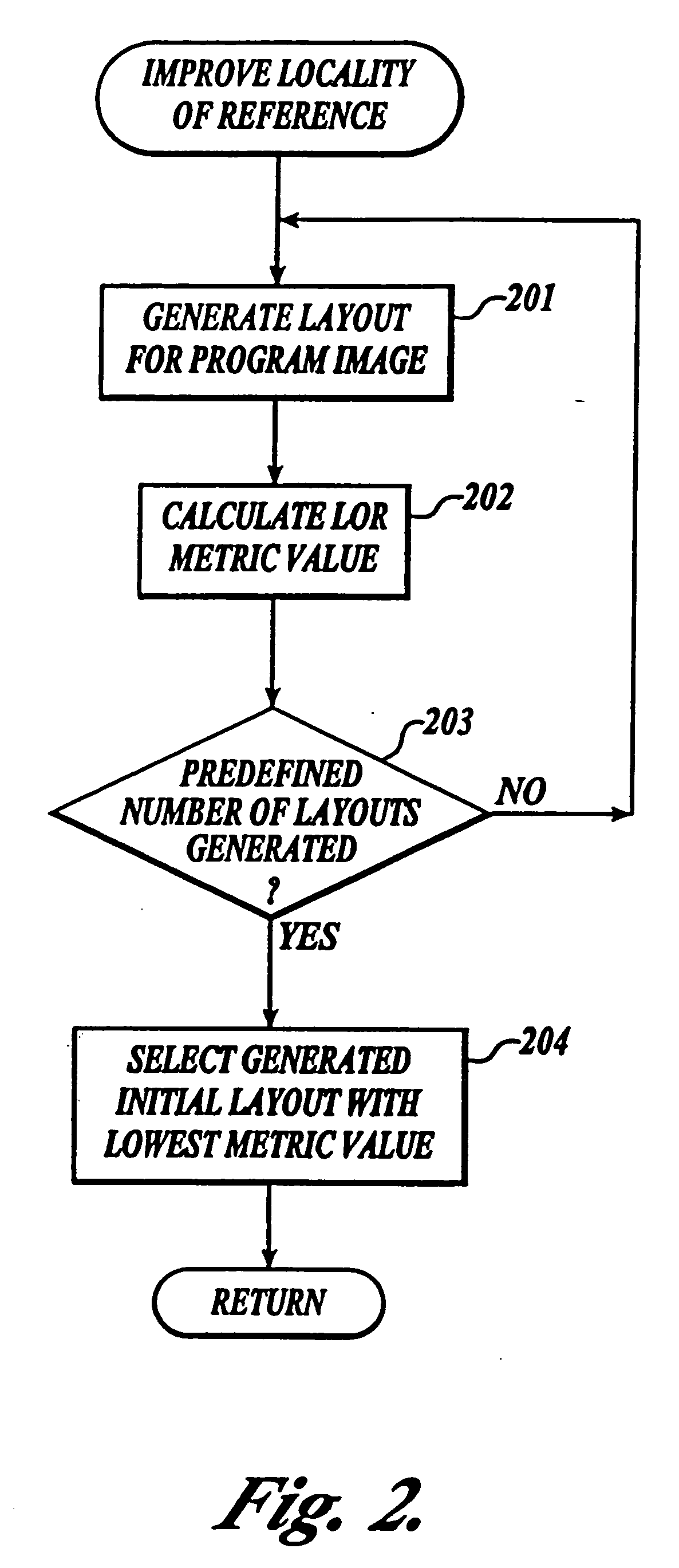
[0044] In the first phase, the WS improvement system generates various different layouts of the program image. The WS improvement system uses a locality of reference (LOR) metric function to evaluate the locality of the references of each layout. The WS improvement system then selects the layout with the best locality of references, as indicated by ...


PUM


Abstract

A method and system for improving the working set of a program image. The working set (WS) improvement system of the present invention employs a two-phase technique for improving the working set. In the first phase, the WS improvement system inputs the program image and outputs a program image with the locality of its references improved. In the second phase, the WS improvement system inputs the program image with its locality of references improved and outputs a program image with the placement of its basic blocks in relation to page boundaries improved so that the working set is reduced.

Description

RELATED APPLICATIONS [0001] This patent application is related to U.S. patent application No.______, entitled “Method and System for Improving the Layout of a Program Image Using Clustering” and U.S. patent application No.______, entitled “Method and System for Incrementally Improving a Program Layout,” which are being filed concurrently and are hereby incorporated by reference.TECHNICAL FIELD [0002] This invention relates to a method and system for optimizing a computer program image and, more particularly, to a method and system for rearranging code portions of the program image to reduce the working set. BACKGROUND OF THE INVENTION [0003] Many conventional computer systems utilize virtual memory. Virtual memory provides a logical address space that is typically larger than the corresponding physical address space of the computer system. One of the primary benefits of using virtual memory is that it facilitates the execution of a program without the need for all of the program to ...

Claims


Application Information

Patent Timeline
IPC IPC(8): G06F9/45G06F9/445
CPCG06F9/44557G06F9/445
Inventor DOUCEUR, JOHN R.FITZGERALD, ROBERT P.MILLER, JOHN W.
Owner MICROSOFT TECH LICENSING LLC
Learn More