
Systems and methods for generating high repetition rate ultra-short optical pulses

a generator and ultra-short technology, applied in the direction of basic electric elements, laser details, electrical equipment, etc., can solve the problems of low synchronization property of mode-locked pulses, generally difficult to meet the assembly requirements of lasers, and generally cannot support a high repetition rate, so as to reduce the noise of mode-locked pulses and minimize the total dispersion

Inactive Publication Date: 2006-11-02
PRECISION PHOTONICS CORP
View PDF4 Cites 50 Cited by
  • Summary
  • Abstract
  • Description
  • Claims
  • Application Information

AI Technical Summary

Benefits of technology

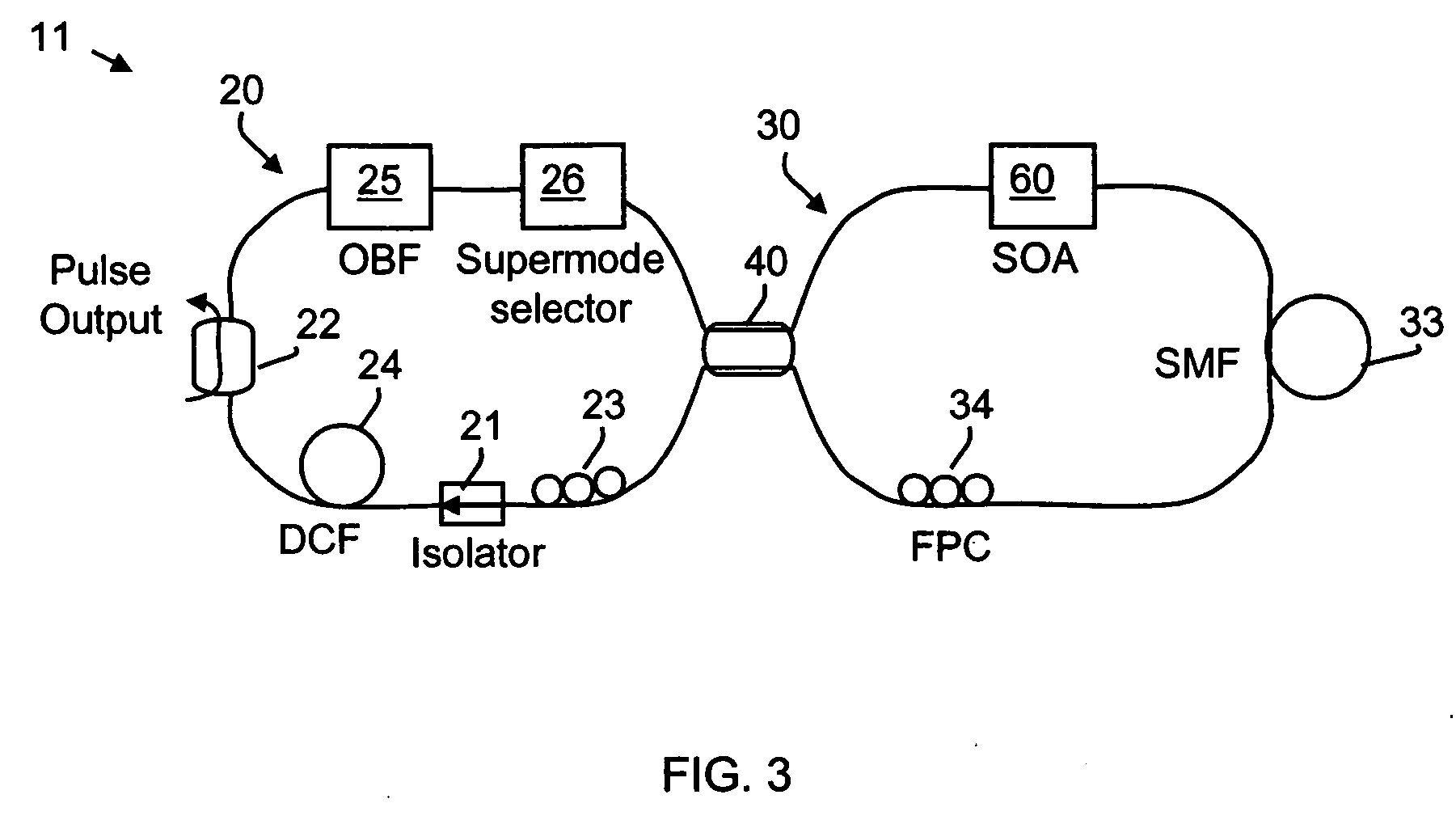
[0010] In some instances of the embodiments, the systems further include a dispersion control section using, for example, an optical fiber with appropriate dispersion and length operable to minimize the total dispersion in the laser cavity. In addition, the systems include a wavelength tuning element that is operable to change the wavelength of light propagated by the optical pulse generation device within a spectral gain profile of the semiconductor optica...

Problems solved by technology

However, such lasers generally have relatively complex assembly requirements involving precise mechanical alignment of bulk-optic components.
However, while existing fiber lasers may be able to generate relatively short optical pulses, they typically cannot support a high repetition rate due to the cavity's low fundamental mode frequency (e.g., less than one hundred megahertz), and the relatively poor synchronization property of the mode-locked pulses due to the self-initiation of the lasing conditions caused by noise fluctuations.
Various approaches may be used to improve repetition rate and pulse synchronization in such lasers, however, these approaches typically result in relatively long pulses (e.g., greater than one picosecond).

Method used


Image

  • Systems and methods for generating high repetition rate ultra-short optical pulses
  • Systems and methods for generating high repetition rate ultra-short optical pulses
  • Systems and methods for generating high repetition rate ultra-short optical pulses

Examples


Embodiment Construction

[0021] The present invention relates generally to optical pulse generators, and more particularly, to mode-locked fiber laser generators of short optical pulses with high repetition rates.

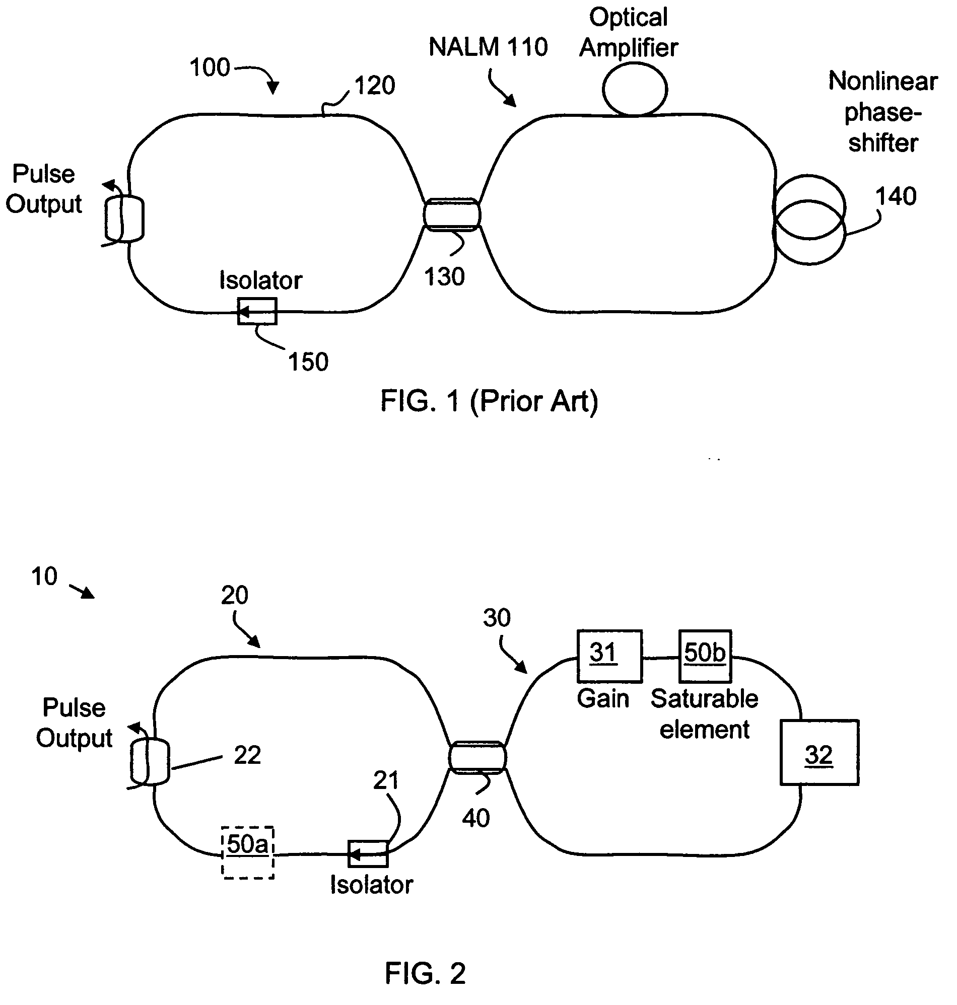
[0022]FIG. 1 illustrates a conventional pulse generating laser 100 based on a ring cavity 120 and a NALM 110 that are connected together by an optical coupler 130 to form a figure-eight laser (hereinafter “F8L”) configuration. In this case, light entering NALM 110 is split into clockwise (hereinafter “CW”) and counterclockwise (hereinafter “CCW”) propagating beams. The CW beam is amplified, using, for example, an erbium-doped fiber amplifier (hereinafter “EDFA”), prior to propagating through an intensity-dependent phase shifter 140. The CCW beam is amplified after propagating through phase shifter 140. The amplified CW and CCW beams return to optical coupler 130 at the same amplitude, but one beam has acquired a nonlinear phase shift relative to the other. This phase shift causes the high intensit...


PUM


Abstract

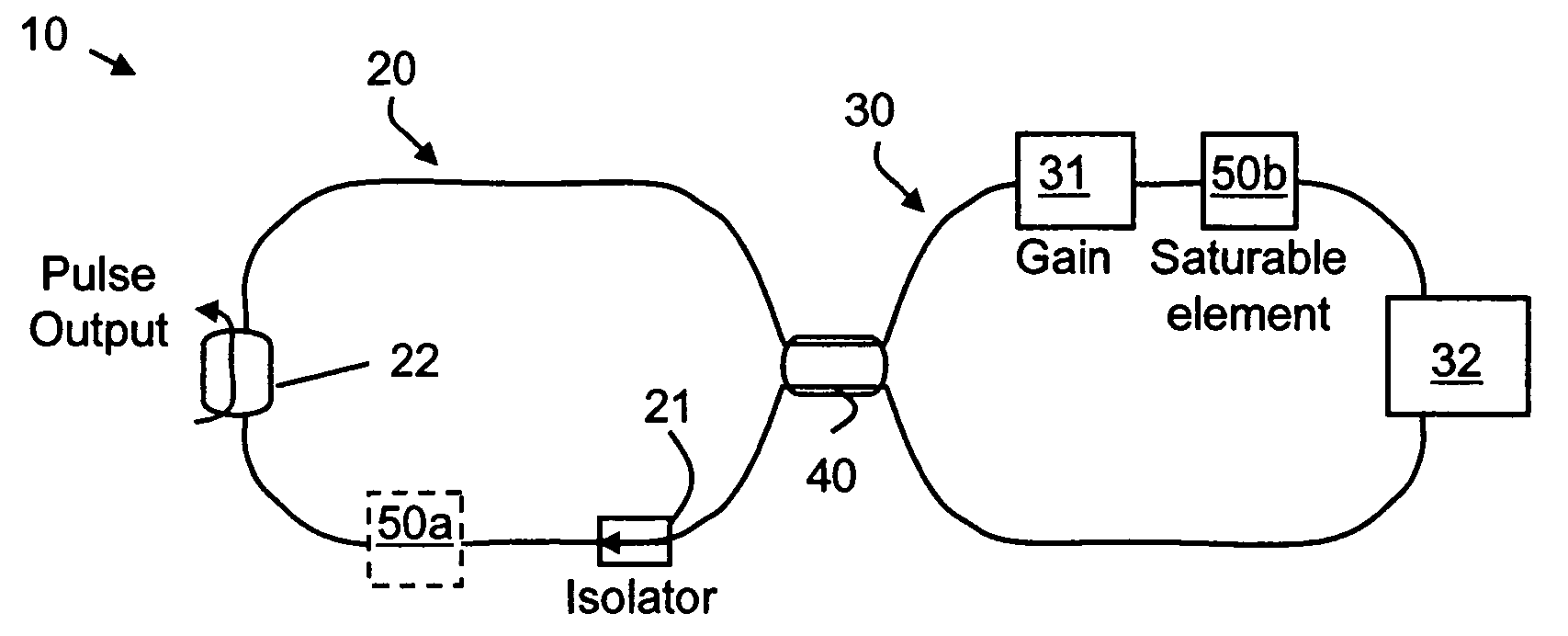
Systems, methods, circuits and / or devices for generating high repetition rate ultra-short pulses are described. As one of many examples, an optical pulse generating laser system is described that produces mode-locked optical pulses. The laser system incorporates an optical pulse generation device that includes two optical loops coupled via a beam splitter. In addition, the optical pulse generation device includes an optical gain medium that is associated with the first optical loop, and a saturable element that is disposed in either the first optical loop or the second optical loop. The saturable element is operable to modulate a group of optical pulses propagating in at least one of the first optical loop and the second optical loop to create a group of substantially regular modulated pulses.

Description

CROSS REFERENCE TO RELATED APPLICATIONS [0001] The present application claims priority to U.S. Provisional Patent Application No. 60 / 675,490 filed on Apr. 21, 2005. The aforementioned provisional patent application is owned by an entity common hereto, and is included herein by reference for all purposes.BACKGROUND OF THE INVENTION [0002] The present invention relates generally to optical pulse generators, and more particularly, to mode-locked fiber laser generators of short optical pulses with high repetition rates. [0003] Various applications require ultra-short optical pulses with megahertz or higher repetition rates. Some examples of the applications include high-speed time-domain-multiplexed optical communication links, signal processing systems employing optical sampling, material processing, and biological imaging. Mode-locked semiconductor lasers have been considered as a vehicle for providing high frequency, ultra-short optical pulses. However, such lasers generally have rel...

Claims


Application Information

Patent Timeline
IPC IPC(8): H01S3/30H01S3/113H01S3/098H01S3/10
CPCH01S3/0064H01S3/06791H01S3/08004H01S3/1305H01S3/1109H01S3/1118H01S3/1062
Inventor LASRI, JACOBVOGEL, KURT R.CLAUSSEN, NEILMYATT, CHRISTOPHER J.
Owner PRECISION PHOTONICS CORP
Learn More