Touch motion switch

a technology of motion switch and touch, which is applied in the direction of mechanical vibration separation, dynamo-electric machines, emergency actuators, etc., can solve the problems of difficult for users to recognize vibration according to the operation of the switch, and the vibration is not concentrated on a contact portion of the user, so as to improve the vibration force, prevent the dispersion of the vibration force, and increase the recognition of vibrations

Inactive Publication Date: 2015-06-18
HYSONIC
View PDF10 Cites 7 Cited by
  • Summary
  • Abstract
  • Description
  • Claims
  • Application Information

AI Technical Summary

Benefits of technology

The touch motion switch described in this patent has the following advantages: 1. The vibration unit vibrates vertically by an electromagnetic interaction of the magnetic force unit and the coil unit, while the second guide moves vertically along the first guide, reducing dispersion of the vibrating force and improving recognition of vibrations by the user. 2. The second guide prevents lateral shaking of the vibration unit, minimizing dispersion of the vibrating force. 3. The magnetic force unit is fixed by the fixing unit, preventing separation from the magnets with the same polarities facing each other. 4. The vibration unit vibrates as a current is applied to the coil, making the switch operate conveniently.

Problems solved by technology

However, in the haptic switch according to the related art, because vibrations are transferred to the entire switch and a device employing the switch when the vibrations are generated, the vibrations are not concentrated on a contact portion of the user but are dispersed.
In particular, in a steering wheel of a vehicle and a switch of an electronic device, because vibrations of the vehicle basically exist and the switch is large as compared with a general portable terminal switch, it may be difficult for a user to recognize vibrations according to an operation of the switch.

Method used


Image

  • Touch motion switch
  • Touch motion switch
  • Touch motion switch

Examples


Embodiment Construction

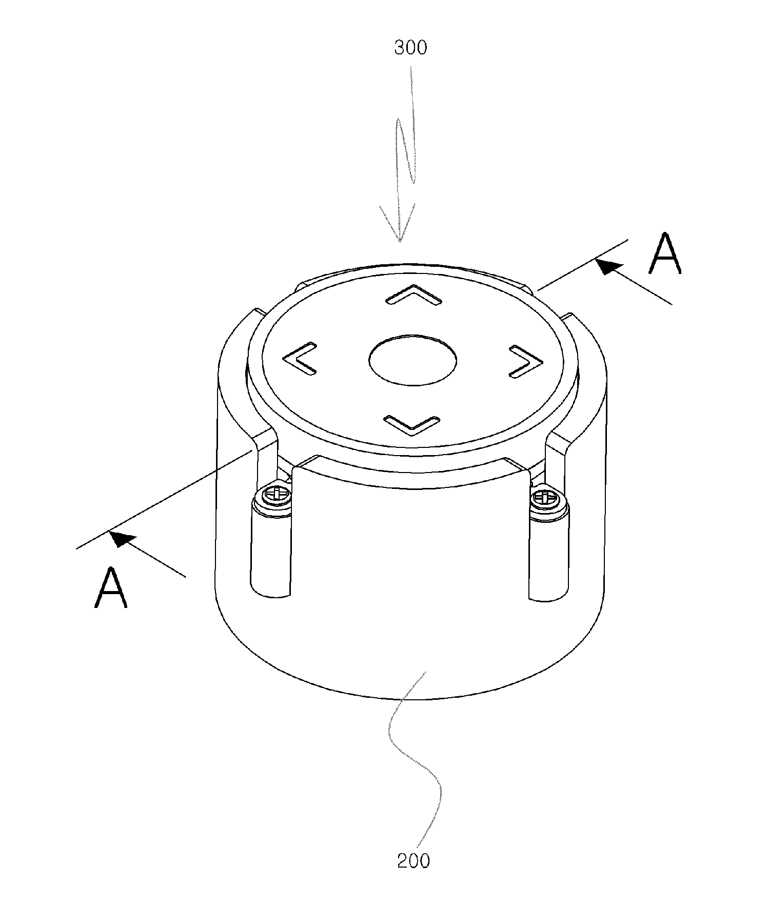
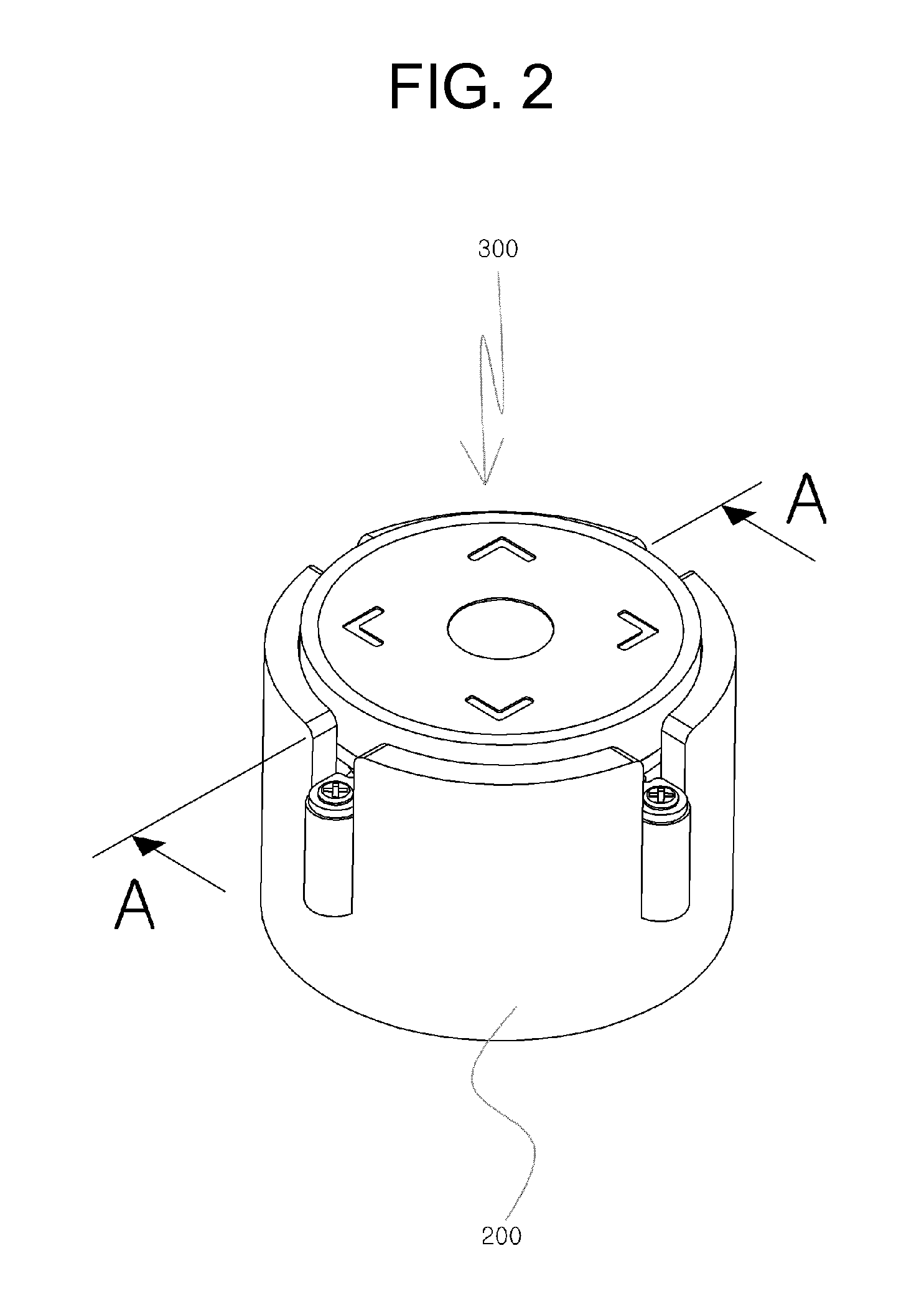
[0029]As shown in FIGS. 2 to 4, a touch motion switch according to an embodiment of the present invention includes a case 200, a vibration unit 300, a resilient member 400, a magnetic force unit 500, a fixing unit 600, and a coil unit 700.

[0030]As shown in FIGS. 2 and 3, the case 200 has a cylindrical shape and has an opened upper side such that the vibration unit 300, the resilient member 400, the magnetic force unit 500, the fixing unit 600, and the coil unit 700 are inserted into the case 200.

[0031]A first guide 210 is formed within the case 200.

[0032]As shown in FIG. 4, the first guide 210 protrudes upwards from an inner lower surface of the case 200 and the magnetic force unit 500 is spaced apart from the first guide 210 on the outer side of the first guide 210.

[0033]In the embodiment of the present invention, the case 200 has a cylindrical shape, but the shape of the case 200 is not limited to the embodiment.

[0034]The case 200 may be installed in a vehicle to operate a steerin...


PUM


Abstract

Disclosed is a touch motion switch, more particularly a touch motion switch which generates vibrations such that a user feels vibrations when touching a switch. The touch motion switch includes: a case having a first guide therein; a vibration unit coupled to the case to be movable vertically and having a second guide movable vertically along the first guide; a resilient member mounted to the case to support the vibration unit and resiliently deformed when the vibration unit is moved vertically; a magnetic force unit inserted into the case; and a coil unit mounted to the second guide, for providing a driving force such that the vibration unit is vertically moved to vibrate by an electromagnetic interaction with the magnetic force unit.

Description

TECHNICAL FIELD[0001]The present invention relates to a touch motion switch, and more particularly to a touch motion switch which generates vibrations such that a user feels vibrations when touching a switch.BACKGROUND ART[0002]Generally, a computer touch technology is called a haptic technology.[0003]Korean Patent No. 10-0877067 discloses a haptic switch for transferring vibrations and various stimuli to a user, and the haptic switch may be applied to input units of various digital devices.[0004]The haptic switch is widely used mainly in small-sized portable terminals, but also may be applied to switches of various electronic devices in vehicles.[0005]FIG. 1 is a view for conceptionally explaining a haptic switch according to the related art.[0006]In the haptic switch according to the related art, two electrodes 32a and 32b contact opposite surfaces of an electro active polymer 31.[0007]Opposite ends of the electro active polymer 31 are fixed to fixing units 33 so as not to be disp...

Claims


Application Information

Patent Timeline
Patent Type & Authority Applications(United States)
IPC IPC(8): H01H13/20H01H13/10H01H13/04
CPCH01H13/20H01H13/04H01H2239/074H01H2215/05H01H2221/024H01H13/10H02K33/02G06F3/016H01H25/041G06F3/0202G06F3/023B06B1/04G06F3/041
Inventor SEO, JONG SIKKIM, MIN GICHUN, SE JUNKIM, YONG KYU
Owner HYSONIC
Why Eureka
Try Eureka