
Piezoelectric thin-film resonator and filter having the same

Active Publication Date: 2006-11-02
TAIYO YUDEN KK
View PDF5 Cites 20 Cited by
  • Summary
  • Abstract
  • Description
  • Claims
  • Application Information

AI Technical Summary

Benefits of technology

[0011] The present invention has been made in view of the above circumstances and provides a piezoelectric thin-film resonator and a filter having the same, which reduce variations in resonance characteristics and filter characteristics and improve the reliability.
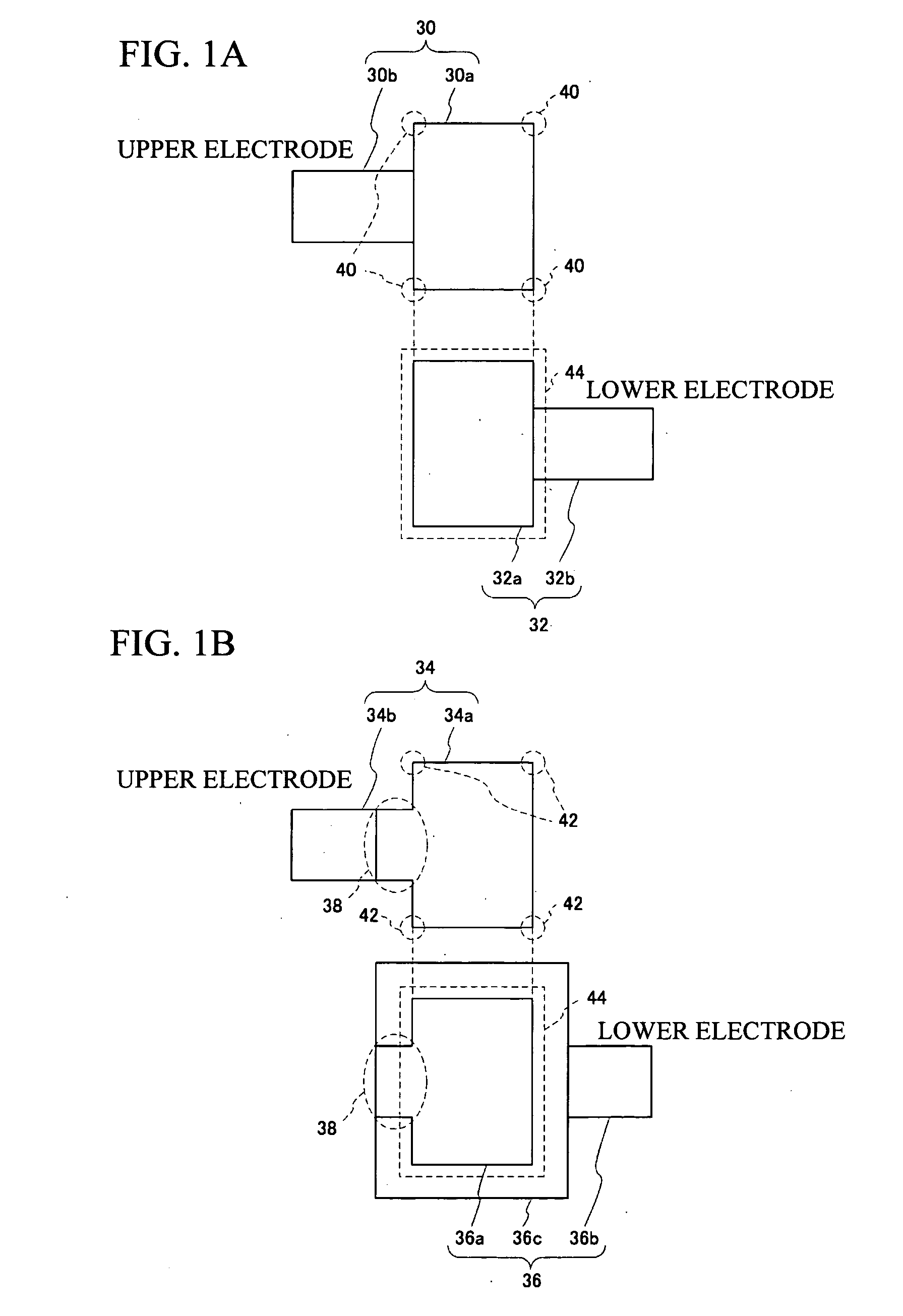
[0012] According to one aspect of the present invention, preferably, there is provided a piezoelectric thin-film resonator including: a lower electrode provided on a substrate; a piezoelectric thin film provided on the lower electrode; and an upper electrode provided on the piezoelectric thin film. A membrane region is defined by a region where the upper electrode and the lower electrode overlap each other to sandwich the piezoelectric thin film therebetween and has an elliptical shape; and the lower electrode is also provided at an outer side of the membrane region in a region in which neither an extraction electrode of the upper electrode nor an extraction electrode of the lower electrode is provided. In accordance with the present invention, the membrane region is retained not only by the extraction electrode of the lower electrode but also by the extension portion, making it possible to suppress the degradation of the membrane region. In addition, the membrane region has an elliptical shape, allowing the stress to be applied equally to the periphery of the membrane region. This also suppresses the degradation of the membrane region, and reduces the variations of the resonance characteristics. It is therefore possible to provide a highly reliable piezoelectric thin-film resonator having reduced variations of the resonance characteristics.
[0013] According to another aspect of the present invention, preferably, there is provided a piezoelectric thin-film resonator including: a lower electrode provided on a substrate; a piezoelectric thin film provided on the lower electrode; an upper electrode provided on the piezoelectric thin film; and a center frequency adjusting film provided on the upper electrode. The center frequency adjusting film is provided to be greater than a membrane region and include the membrane region, in which the upper electrode and the lower electrode overlap each other to sandwich the piezoelectric thin film therebetween. In accordance with the present invention, the adherence in the membrane region is improved, thereby suppressing the degradation of the membrane region. This makes it possible to provide a highly reliable piezoelectric thin-film resonator.

Problems solved by technology

There exist problems, however, in Conventional Art 1, Conventional Art 2, and Conventional Art 3, in that the resonance characteristics and the filter characteristics vary depending on the variation caused by the fabrication process.
In addition, there exist other problems in Conventional Art 4 and Conventional Art 5 in that the resonance characteristics and the filter characteristics are degraded.
Furthermore, Conventional Arts 1 through 5 suffer from a common problem of low reliability.

Method used


Image

  • Piezoelectric thin-film resonator and filter having the same
  • Piezoelectric thin-film resonator and filter having the same
  • Piezoelectric thin-film resonator and filter having the same

Examples


first embodiment

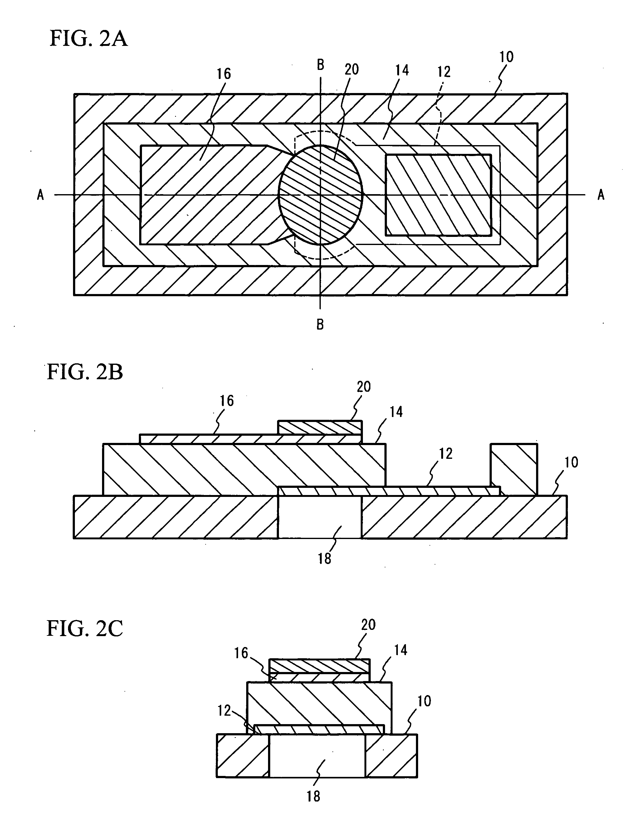
[0035]FIG. 2A through FIG. 2C are views illustrating a configuration of a piezoelectric thin-film resonator in accordance with a first embodiment of the present invention. FIG. 2A is a top view of the piezoelectric thin-film resonator in accordance with the first embodiment of the present invention. FIG. 2B is a cross-sectional view taken along a line A-A shown in FIG. 2A. FIG. 2C is a cross-sectional view taken along a line B-B shown in FIG. 2A. A lower electrode 12 is provided on a silicon substrate 10. A piezoelectric thin film 14 is provided on the lower electrode 12. An upper electrode 16 is provided on the piezoelectric thin film 14. A membrane region 22 corresponds to a region in which the upper electrode 16 and the lower electrode 12 overlap each other to sandwich the piezoelectric thin film 14. The piezoelectric thin film 14 provided on the lower electrode 12 is partially removed and a hole for connection is formed. A space 18 having the same size as that of the membrane re...

second embodiment

[0051] Another example of the resonator will be described in a second embodiment of the present invention. The resonator employed in the second embodiment has an enlarged region in which a silicon oxide film that serves as the center frequency adjusting film 20 is to be formed. FIG. 8A is a top view of the resonator employed in the first embodiment, and does not show the center frequency adjusting film 20. FIG. 8B shows a region of the center frequency adjusting film 20 in the resonator shown in FIG. 8A. As shown in FIG. 8B, the center frequency adjusting film 20 is formed only in the membrane region 22.

[0052]FIG. 8C shows a region in which a center frequency adjusting film 20a is formed in accordance with the second embodiment. The center frequency adjusting film 20a is formed in a region except windows provided for bonding the upper electrode 16 and the lower electrode 12. That is, the center frequency adjusting film 20a is formed greater than the membrane region 22 to include th...


PUM


Abstract

A piezoelectric thin-film resonator includes a lower electrode provided on a substrate, a piezoelectric thin film provided on the lower electrode, and an upper electrode provided on the piezoelectric thin film. A membrane region is defined by a region where the upper electrode and the lower electrode overlap each other to sandwich the piezoelectric thin film therebetween and has an elliptical shape, and the lower electrode is also provided at an outer side of the membrane region in a region in which neither an extraction electrode of the upper electrode nor an extraction electrode of the lower electrode is provided.

Description

BACKGROUND OF THE INVENTION [0001] 1. Field of the Invention [0002] This invention generally relates to piezoelectric thin-film resonators and filters, and more particularly, to a piezoelectric thin-film resonator and a filter having the same, in which an upper electrode and a lower electrode are provided to overlap each other and sandwich a piezoelectric thin film therebetween in a region having an elliptical shape. [0003] 2. Description of the Related Art [0004] With the rapid spread of high-frequency wireless devices, as represented by mobile telephones, there is more demand for small-sized and lightweight high frequency filters for use in high frequency bands of 900 MHz to 5 GHz. Filters that mainly include surface acoustic wave devices are utilized in the afore-mentioned field. In these days, however, an attention is being focused on a piezoelectric thin-film resonator and a filter having the same, because the device is excellent in high frequency characteristics, can be downsi...

Claims


Application Information

Patent Timeline
IPC IPC(8): H03H9/56H01L41/08H01L41/09H01L41/18H01L41/22H01L41/253H01L41/29H03H9/17
CPCH03H3/04H03H9/132H03H2003/0457H03H9/174H03H2003/0428H03H9/173H03H9/15
Inventor YOKOYAMA, TSUYOSHINISHIHARA, TOKIHIROTANIGUCHI, SHINJISAKASHITA, TAKESHITSUTSUMI, JUNIWAKI, MASAFUMIUEDA, MASANORI
Owner TAIYO YUDEN KK
Learn More