
Inserting anterior and posterior spinal prostheses

a spinal column and prosthesis technology, applied in the field of human prosthesis, can solve the problems of disadvantageous rigid stabilization (fusion) of the spinal column, large vessel retraction, complex procedure, etc., and achieve the effect of minimizing human error

Active Publication Date: 2006-10-26
PREMIA SPINE
View PDF17 Cites 77 Cited by
  • Summary
  • Abstract
  • Description
  • Claims
  • Application Information

AI Technical Summary

Benefits of technology

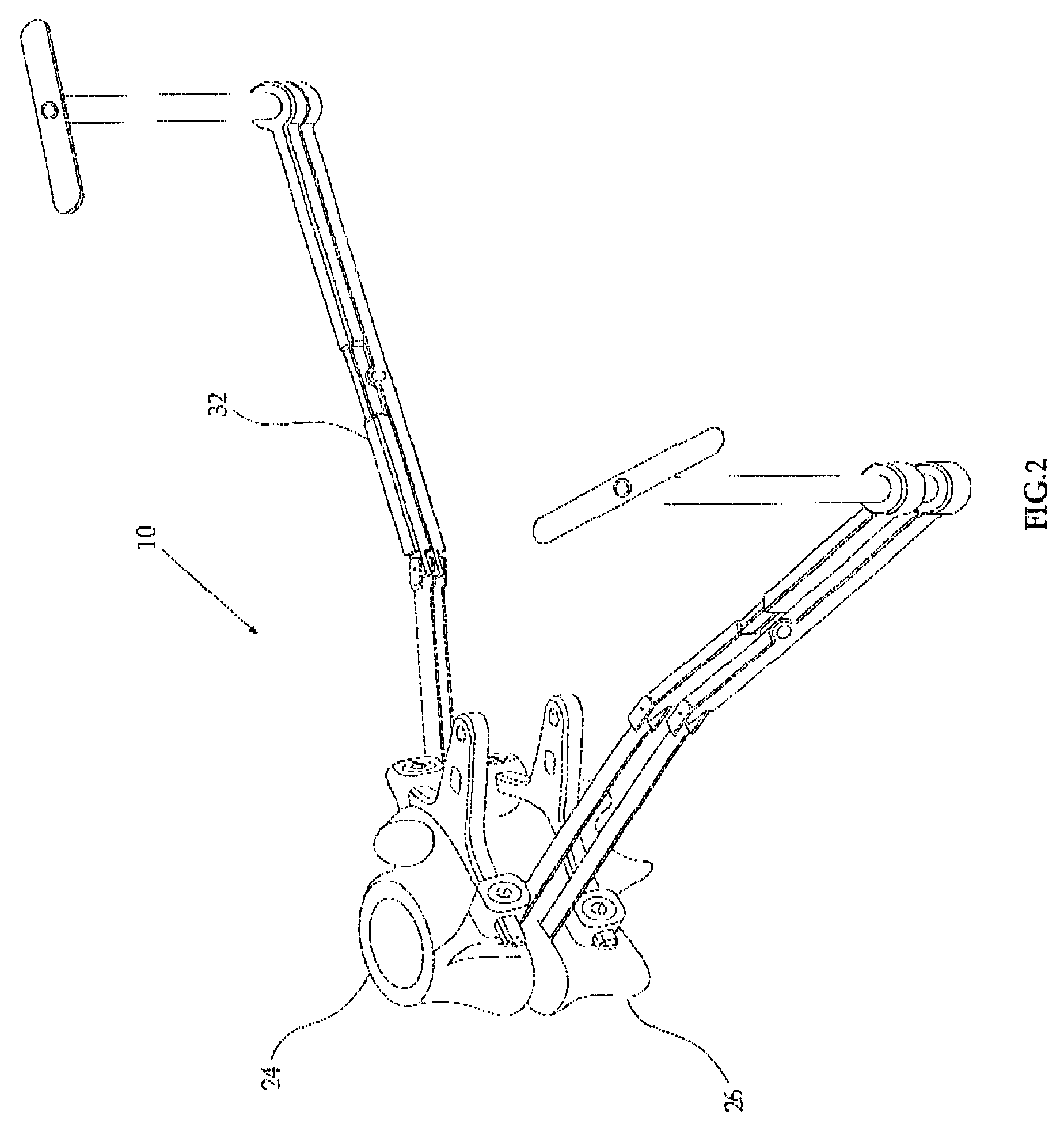
[0008] The device may define a trajectory or path or reference point, for the insertion of the disc prosthesis. This trajectory or path or reference point ensures that the implanted disc will be placed in a predetermined position in relation to the pre-inserted screws. Since the screws are in a known position in relation to the vertebra and to a posterior implant to be subsequently placed onto the pedicle screws, this device will aid in the placement of the disc prosthesis preferably via a transforaminal approach (such a disc insertion approach being known in the art) in an accurate position in relation to both the vertebrae and to the posterior implant, thus minimizing human error. The positioning of the pedicle screws defines the positioning of the posterior prosthesis.

Problems solved by technology

Rigid stabilization (fusion) of the spinal column can be disadvantageous due to migration of the problems to adjacent level in the spinal column.
This is a complex procedure often involving extensive vessel retraction among other difficulties.

Method used


Image

  • Inserting anterior and posterior spinal prostheses
  • Inserting anterior and posterior spinal prostheses
  • Inserting anterior and posterior spinal prostheses

Examples


Embodiment Construction

[0022] Before explaining at least one embodiment of the invention in detail, it is to be understood that the invention is not limited in its application to the details of construction and the arrangement of the components set forth in the following description or illustrated in the drawings. The invention is capable of other embodiments or of being practiced or carried out in various ways. Also, it is to be understood that the phraseology and terminology employed herein is for the purpose of description and should not be regarded as limiting.

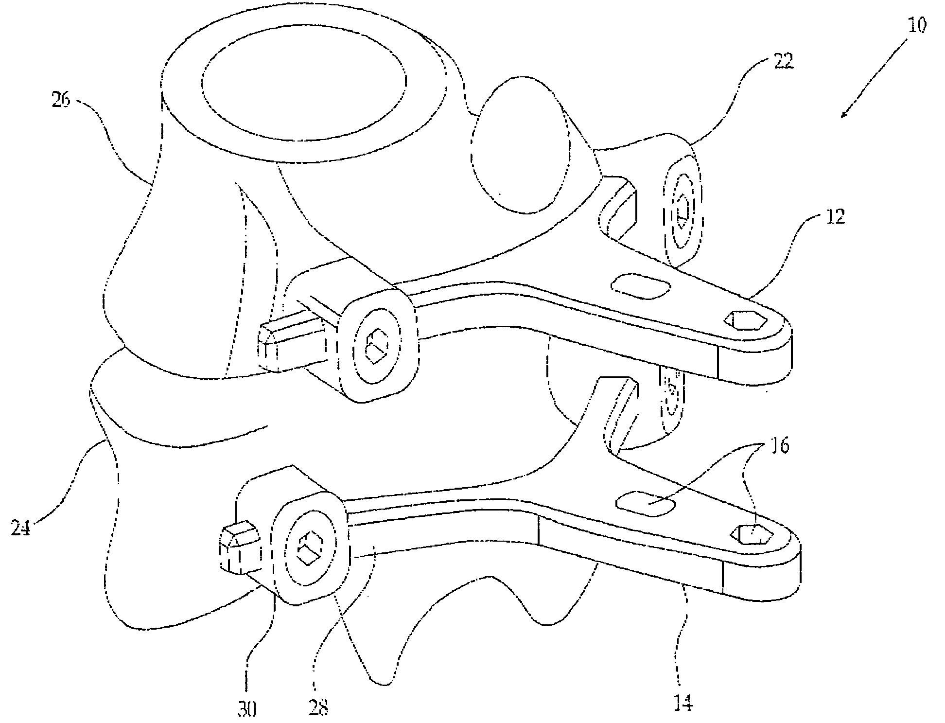
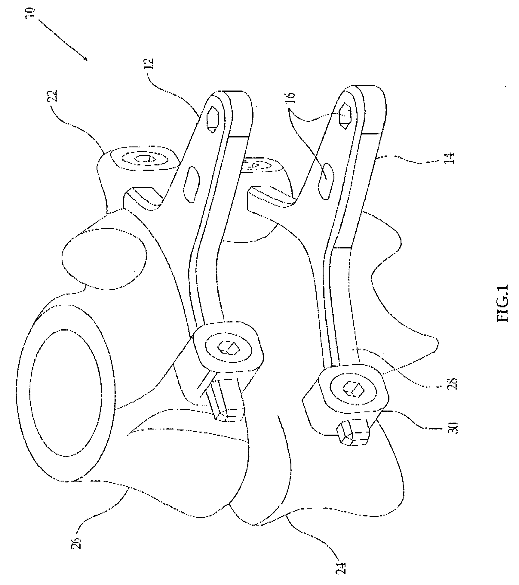
[0023] Reference is now made to FIG. 1, which illustrates a positioning adapter 10 attached to four pedicle screws 22 which are anchored into two adjacent vertebrae, for example, L4 24 and L5 26. The screws 22 were initially placed into the pedicle of the vertebrae as is known to those skilled in the art. The pedicle screws 22 may be used, for example, to anchor a posterior spinal prosthesis to the pedicles.

[0024] Although four pedicle screws ...


PUM


Abstract

Spinal apparatus including reference structure spatially fixed relative to a plurality of pedicle screws that are mounted in adjacent vertebrae of a patient, and a device connected to the reference structure which is adapted to install an anterior spinal prosthesis, wherein the reference structure defines a spatial relationship between the anterior spinal prosthesis and a posterior spinal prosthesis attached to the pedicle screws.

Description

CROSS-REFERENCE TO RELATED APPLICATIONS [0001] This application claims priority under 35 USC §119 to U.S. Provisional Patent Application Ser. No. 60 / 669,902, filed Apr. 11, 2005, and U.S. Provisional Patent Application Ser. No. 60 / 757,467, filed Jan. 10, 2006, which are incorporated herein by reference. FIELD OF THE INVENTION [0002] The present invention relates to human prostheses, and more particularly to spinal column vertebral disc prosthesis in conjunction with posterior spinal prostheses and methods for the insertion and harmonious coordination between the prostheses. BACKGROUND OF THE INVENTION [0003] A common procedure used for stabilizing the vertebral column is bracing adjacent vertebrae by connecting rigid or resilient connecting implants to anchor members such as pedicle screws. Rigid stabilization (fusion) of the spinal column can be disadvantageous due to migration of the problems to adjacent level in the spinal column. Dynamic stabilization provided by resilient impla...

Claims


Application Information

Patent Timeline
IPC IPC(8): A61B17/58
CPCA61B17/70A61B17/7062A61B17/86A61B2017/0256A61F2/4405A61F2220/0091A61F2002/30471A61F2002/3052A61F2002/4622A61F2002/4628A61F2220/0025A61F2/4611A61B17/88A61F2/44A61F2/46
Inventor ARNIN, URIFLEISCHER, SHAI
Owner PREMIA SPINE
Learn More