Eureka AIR delivers breakthrough ideas for toughest innovation challenges, trusted by R&D personnel around the world.

Hydro-Oxy fuel generator

Inactive Publication Date: 2006-10-26
FOSTER JESSE
View PDF2 Cites 5 Cited by
  • Summary
  • Abstract
  • Description
  • Claims
  • Application Information

AI Technical Summary

Benefits of technology

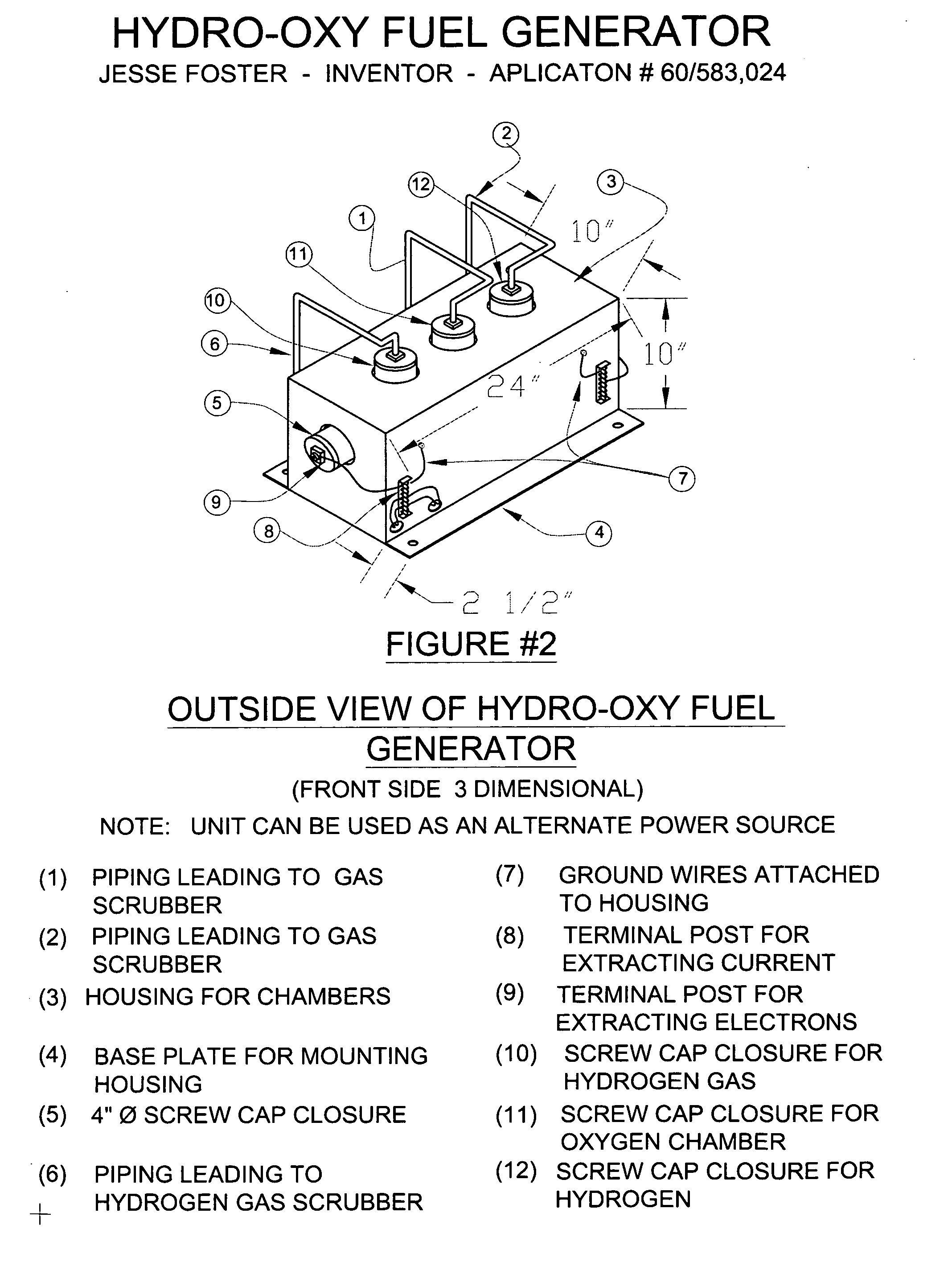
[0004] The applicants invention provides a portable means of generating hydrogen and oxygen gas on-board vehicles or other remote places where the gases can be used as an alternative fuel. The oxygen that the system produces is used to complete hydrogen combustion, thus, eliminating the need of oxygen being taken from the atmosphere. The invention can be readily attached to hydrogen fuel cells and hydrogen combustion engines. The only raw material required for the system is ionized water. The nature of this invention is to make use of the chemical principals involving the electrolysis of water to create an alternate fuel source for autos, trucks, buses, businesses, camps, and communications that presently use fossil fuel as an energy source. The Hydro-Oxy Fuel Generator is a system that is portable enough to be used on-board any vehicle to generate Hydrogen and Oxygen, which in tern, can be used as a fuel. However, the main thrust of this invention is the portable nature of the system, and the only raw material required to maintain a working performance is water.

Problems solved by technology

The utilization of hydrogen fuel cells and hydrogen combustion engines require large volumes of hydrogen gas to be stored on-board vehicles and require new infrastructure which is presently not feasible.
Presently, hydrogen fuel cells and hydrogen combustion require large volumes of oxygen to complete combustion.
This causes problems with the environment.

Method used


Image

  • Hydro-Oxy fuel generator
  • Hydro-Oxy fuel generator
  • Hydro-Oxy fuel generator

Examples


Embodiment Construction

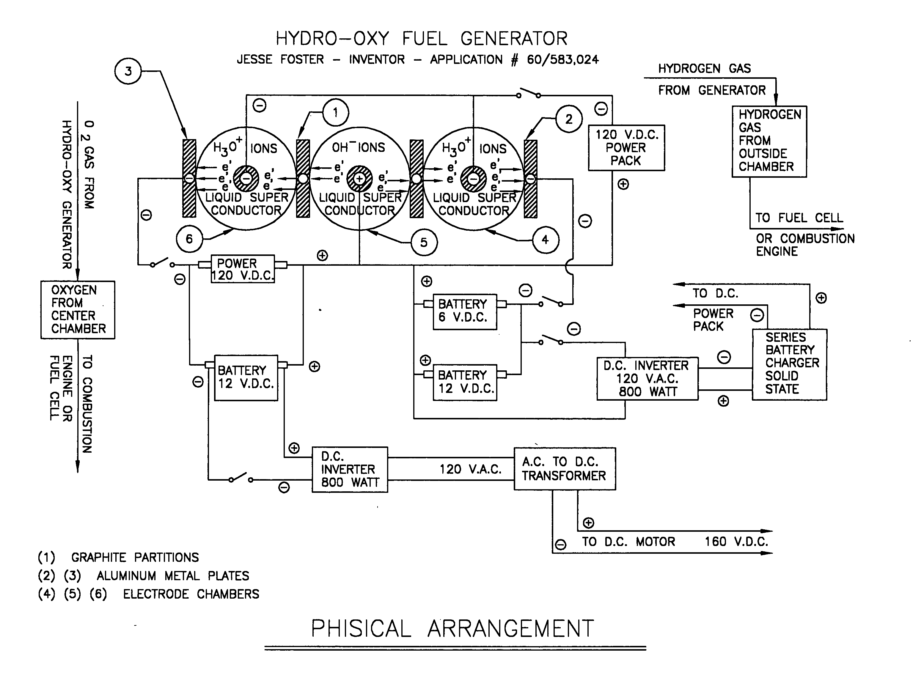
[0005] This invention requires the molecular conversion of ionized water to gases (Hydrogen and Oxygen). The molecular conversion of ionized water to gases take place when a D.C. current is applied. A chemical electrolyte is added to the water to enhance the ionization process. The applicant has selected Double Salts for the electrolyte to enhance the production of the Hydronium ions (H30+) and the hydroxide ions (OH-).

PHYSICAL DESCRIPTION OF INVENTION

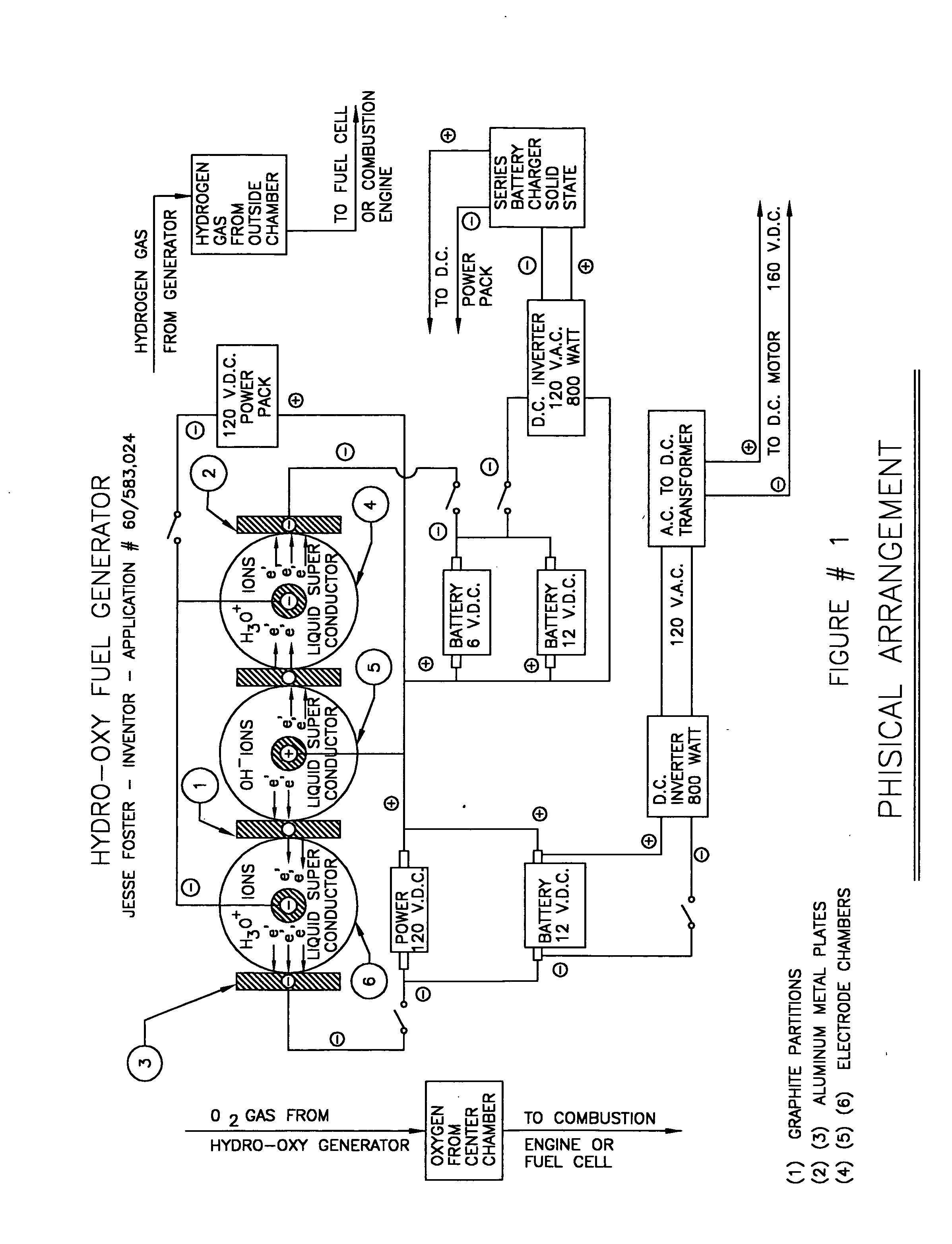
[0006] The Hydro-Oxy Fuel Generator is comprised of three cylindrical chambers. Each chamber can house approximately one gallon of a special electrolyte. Each chamber consist of a set of metal plates that serves as electrodes. the electrode plates are mounted in the center of each chamber from the bottomside. The electrodes always remains submerged in the electrolyte. The liquid level of the electrolyte in each chamber is controlled by a liquid level device mounted in each chamber. See FIGS. 6, 7, &8 for details. The surface area of ...


PUM

PropertyMeasurementUnit
Massaaaaaaaaaa
Volumeaaaaaaaaaa
Currentaaaaaaaaaa

Abstract

The Hydro-Oxy Fuel Generator is an electro / chemical system that can convert ionized water into its molecular components (Hydrogen and Oxygen). The system is portable and can mounted on-board in a stationary position on vehicles (cars, trucks, buses, trains, etc.) that uses hydrogen and oxygen as an alternative fuel source. The basic objective of this invention is to create a viable alternative fuel source that replaces fossil fuels. The system is to have three reaction chambers that are adjacent but separated by a Graphite partition which allow only electrons to travel from one chamber to another. Each chamber is partially filled with an electrolyte. The center chamber house the Anode electrode and the two outside chambers house the Cathode electrode. When D.C. current is applied to the electrodes housed in the chambers (negative terminal is connected to the cathode electrodes and positive terminal is connected to the anode electrode), hydrogen gas is liberated in the two outside chambers and oxygen is liberated in the center chamber. The production of oxygen by the system makes it possible to eliminate the need for taking oxygen from the atmosphere to complete the combustion process when using Hydrogen Fuel cells and Hydrogen combustion engines.

Description

FIELD OF THE INVENTION [0001] This invention is an Electrical / Chemical System that can convert ionized water into its molecular components (Hydrogen and Oxygen gas). The system is portable enough to be mounted on vehicles (cars, trucks, buses, trains, and etc). The purpose of the invention is to produce gases that can be used as a fuel source for Hydrogen Fuel Cells, Fossil Fuel Oxidizers, and Hydrogen Combustion engines. BACKGROUND OF THE INVENTION [0002] The utilization of hydrogen fuel cells and hydrogen combustion engines require large volumes of hydrogen gas to be stored on-board vehicles and require new infrastructure which is presently not feasible. Presently, hydrogen fuel cells and hydrogen combustion require large volumes of oxygen to complete combustion. This oxygen is presently being taken from the atmosphere. This causes problems with the environment. THE HYDRO-OXY FUEL GENERATOR produces both hydrogen and oxygen on-board vehicles (as needed). thus, eliminating the need...

Claims


Application Information

Patent Timeline
IPC IPC(8): C25B1/02
CPCC25B1/06C25B9/06Y02E70/20Y02E60/366Y02E70/10H01M8/0656Y02E60/50Y02E60/36C25B1/04C25B11/00C25B9/17
Inventor FOSTER, JESSE
Owner FOSTER JESSE
Why Eureka
Eureka Blog
Learn More