
Active intake muffler

a technology of active intake and muffler, which is applied in the direction of intake silencer combination, air cleaner for fuel, air cleaner and noise cancelling, etc. it can solve the problems of disturbing noise attenuation, failure to realize the desired compensation, and inability to superimpose with the reflected sound, so as to simplify the installation of the intake muffler and reduce the exposure of the transducer to thermal stress. , the effect of reducing the exposure of the transducer to thermal stress

Inactive Publication Date: 2006-10-26
BENTELER AUTOMOBILTECHNIK GMBH
View PDF13 Cites 17 Cited by
  • Summary
  • Abstract
  • Description
  • Claims
  • Application Information

AI Technical Summary

Benefits of technology

[0012] Loudspeakers of this type can be made flat. The diaphragm is thin and can be made planar or slightly curved. A flat configuration of the diaphragm significantly simplifies a calculation of bending waves and the overall configuration of the diaphragm. In addition, larger diaphragms can be made more compact and may be disposed, for example, in close proximity to the air intake duct.
[0026] According to another feature of the present invention, the transducer may be constructed as an oscillation coil. Use of an oscillation coil results in a compact configuration and arrangement of few moving parts. As an alternative, the transducer may include an electric motor having a driveshaft, with an eccentric secured to the driveshaft and coupled to the diaphragm via a connecting rod. In this way, the frequency of the vibrating diaphragm can be adjusted in an especially easy and robust manner. The electric motor may be placed separate and away from the intake air flow, thereby significantly decreasing the exposure of the transducer to thermal stress. In addition, the transducer may be constructed heat-resistant.

Problems solved by technology

These types of passive mufflers retain the intake air so that engine performance is adversely affected.
As a result of the interference, the disturbing noise is attenuated.
As a consequence of the time that is required for the sound to travel twice along the length of the λ / 4 pipe and due to dynamic conditions that result in a change in frequency of the air intake noise in the air intake ducts, the superimposition with the reflected sound fails to realize the desired compensation.
Moreover, the frequencies where complete suppression is possible are limited to a multiple of λ / 4 for physical reasons.
Establishing physical parameter in connection with reduction of air intake noise is very difficult.
Conventional cone loudspeakers used heretofore for attenuating air intake noise are unable to cope with the rough physical conditions.
In other words, the diaphragm and magnets wear off quickly.
A proposal to use diaphragms of titanium has been discarded because of the prohibitively expensive costs for mass production.
In order to generate low frequencies, large-area diaphragms and heavy magnets are required which however are too bulky for installation in the available space in motor vehicles and unsuitable for large-scale production in view of their weight.

Method used


Image

  • Active intake muffler
  • Active intake muffler

Examples


Embodiment Construction

[0029] The depicted embodiment is to be understood as illustrative of the invention and not as limiting in any way. It should also be understood that the drawings are not necessarily to scale and that the embodiments are sometimes illustrated by graphic symbols, phantom lines, diagrammatic representations and fragmentary views. In certain instances, details which are not necessary for an understanding of the present invention or which render other details difficult to perceive may have been omitted.

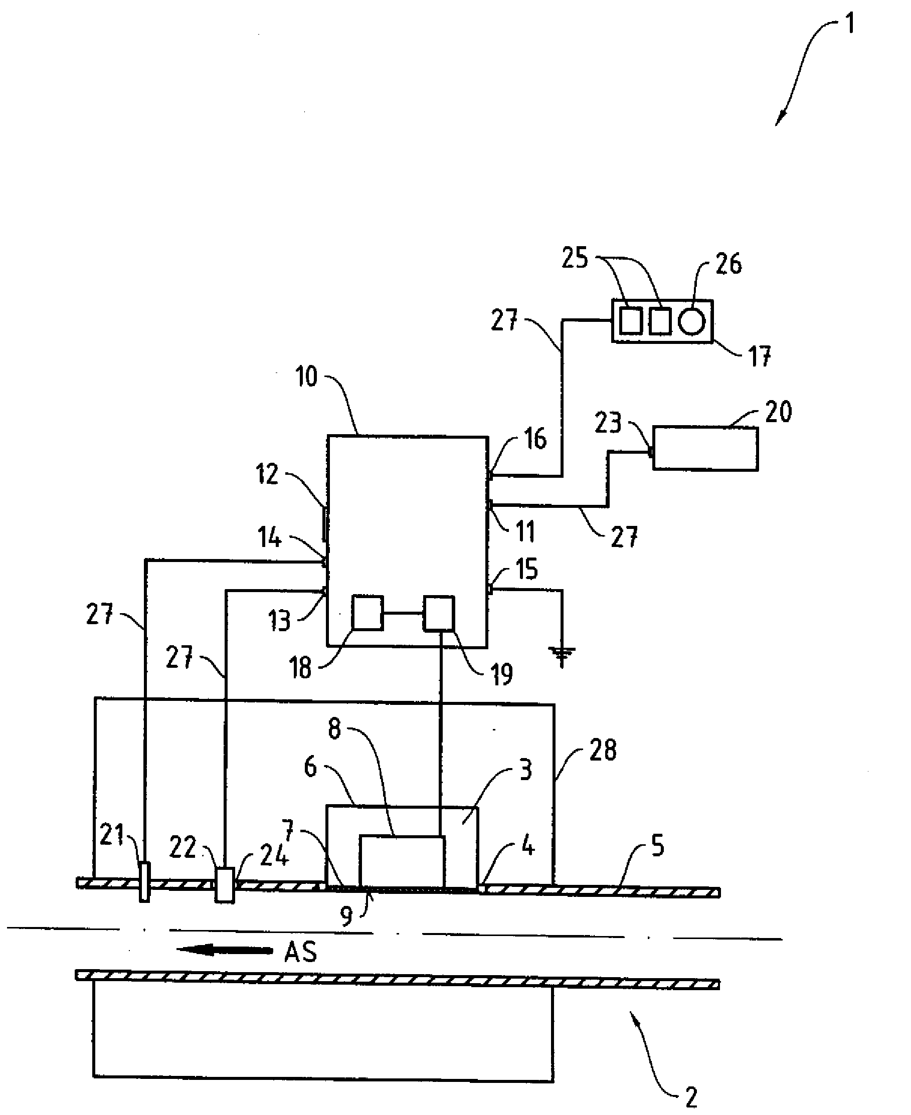
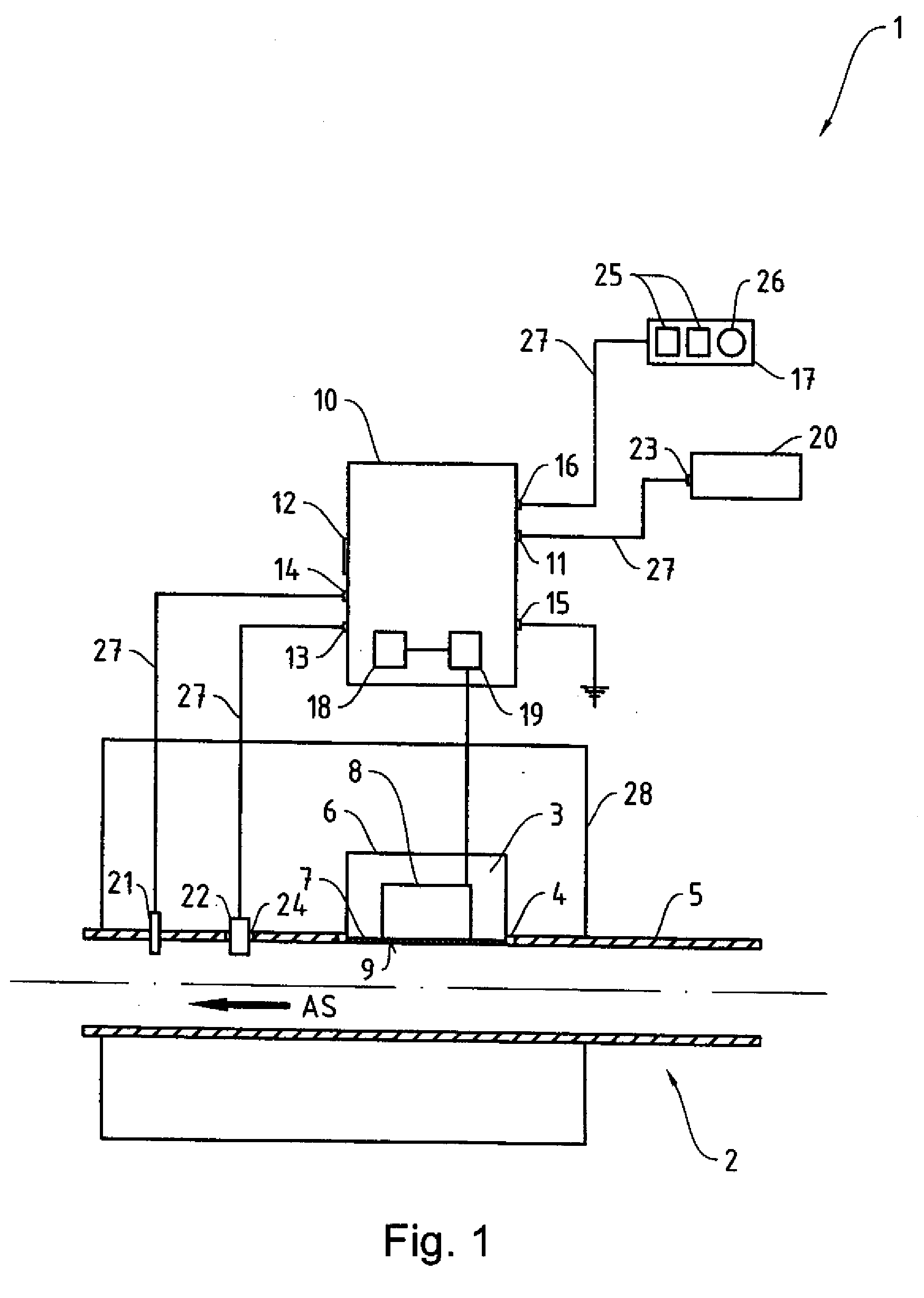
[0030] Turning now to FIG. 1, there is shown a partial longitudinal section of an active intake muffler according to the present invention, generally designated by reference numeral 1, for an air intake duct 2 that may find application for example in a motor vehicle and is arranged in an air filter unit 28. The active intake muffler 1 is provided to superpose the noise, caused by intake of combustion air into internal combustion engine, with a 180° phase-shifted compensation sound of a l...


PUM


Abstract

An active intake muffler for an air intake duct of an internal combustion engine includes a control unit, a sensor assembly operatively connected to the control unit, and a diaphragm constructed to be resistant to heat and moisture. The diaphragm is acoustically coupled with a flow of intake air in the air intake duct and has a surface which confronts the flow of intake air. A transducer is operated by the control unit for causing the surface of the diaphragm to vibrate in a bending vibration mode to thereby produce a structure-bone sound in dependence on noise caused by the intake of air.

Description

CROSS-REFERENCES TO RELATED APPLICATIONS [0001] This application claims the priority of German Patent Application, Serial No. 10 2005 019 459.1, filed Apr. 25, 2005, pursuant to 35 U.S.C. 119(a)-(d), the content of which is incorporated herein by reference. [0002] Reference is also made to commonly assigned copending patent application by the same inventive entity, entitled “Active Exhaust-Noise Attenuation Muffler”, Appl. No. 11 / 373,831, filed Mar. 10, 2006, the disclosure of which is incorporated herein by reference. BACKGROUND OF THE INVENTION [0003] The present invention relates, in general, to an active intake muffler for an air intake duct of an internal combustion engine. [0004] Nothing in the following discussion of the state of the art is to be construed as an admission of prior art. [0005] Air induction systems of motor vehicles typically include an intake muffler to reduce the intensity of noise, caused by intake of combustion air into the internal combustion engine, to a...

Claims


Application Information

Patent Timeline
Patent Type & Authority Applications(United States)
IPC IPC(8): F02M35/12F02M35/14F01N1/06
CPCF02M35/1222F02M35/125
Inventor SEIBT, OLIVERBUSH, GRAHAM
Owner BENTELER AUTOMOBILTECHNIK GMBH
Learn More