Passive entry sensor system

a sensor system and passive technology, applied in the field of passive sensor systems, can solve the problems of difficult specific action, time-consuming and unergonomic, loss or damage of keys, etc., and achieve the effect of minimizing the number of components and limiting the power consumption of the passive sensor system

Inactive Publication Date: 2006-10-19
HONEYWELL INT INC
View PDF6 Cites 28 Cited by
  • Summary
  • Abstract
  • Description
  • Claims
  • Application Information

AI Technical Summary

Benefits of technology

[0014] It is an additional aspect of the present invention to provide for an improved passive entry sensor and system which can be utilized with an access control system for allowing access to a vehicle.
[0016] The sensor system comprises a sensor having an electromagnetic radiation emitter, such as an infra red (IR) light emitting diode (LED), for transmitting a beam of electromagnetic radiation and an electromagnetic radiation detector, such as an IR photo-detector, for detecting the electromagnetic radiation beam. The emitter and detector are located in an optical enclosure of the sensor. At least a portion of the optical enclosure is mountable in a handle of a door or like structure such that the sensor can detect at least a partial interruption or other change in transmission of the beam caused by the user actuating the handle. The senor can be configured to provide an output control signal in response detecting the change in transmission which signal can be provided to an access control mechanism, such as for example a computer processing unit (CPU) of a vehicle, to unlock the door. Mounting at least a portion of the optical enclosure in the handle itself avoids the need to use light pipes to optically couple the sensor to the handle. This arrangement therefore simplifies construction of the passive entry sensor system in the door handle assembly.
[0018] The system can include an independent optical locking switch having a shutter for intercepting and controlling transmission of the beam. The sensor can be configured to detect at least a partial interruption or other change in transmission of the beam caused by actuation of the shutter. By providing an independent locking switch that is operable by the user for locking the door, the functionality of the sensor system is improved. Moreover, utilizing a shutter in the locking switch to control transmission of the beam such that the sensor detects actuation of the locking switch, obviates the need to utilize a microswitch and associated circuitry to provide the output control signal for locking the door. Consequently, this arrangement simplifies construction of the passive entry sensor system and reduces manufacturing costs and assembly time.
[0023] The power-up switch can be included in the sensor for activation by a user to provide a signal to the control module to power up the passive entry system. The power up switch can be arranged on the sensor and operatively coupled to the switch member such that actuation of the switch member triggers the power-up switch. The passive entry system, after being powered down, can be reactivated by actuating the power-up switch as required. The power-up switch provides further functionality to the system and is advantageous in that it allows power consumption of the passive sensor system to be limited.
[0026] Light sources, such as LEDs, can be located in the sensor optical enclosure for illuminating the switch member to indicate one or more system modes, such as alarm activated, right-left turn vehicle indication, locked or unlocked door status, and for providing back and / or ground lighting. Activation of the LEDs can be controlled by a control module, such as the vehicle CPU. The sensor can include one or more LEDs and one or more lens or other optical element for allowing passage of light from the sensor through one or more corresponding handle apertures such that, when the at least part of the optical enclosure is incorporated in the handle, the or each LED can illuminate the door beneath the hand and / or the ground below the handle to provide the back and / or ground lighting.

Problems solved by technology

One problem with the existing key and lock arrangements is that loss or damage to the key can render access impossible.
One other problem is that the use of a key requires a specific action such as unlocking a latch with the key from the authorized person before an action of opening the door.
This specific action is very often not easy to do, not ergonomic and is time-consuming.
One problem with this arrangement is that the user still has to initiate a specific action such as, in the case of a fob, taking the fob in his hand and pressing on the fob button, or in the case of a magnetic card or the like, inserting the card in a slot or to present it in front of a card reader / detector or the like, in order to unlock the door and have access to the vehicle, these specific actions being time-consuming and not ergonomic.
One other problem with this arrangement is that if the user decides not to enter the vehicle but forgets to actuate the “lock” signal, the car and / or building remains open and is thus vulnerable.
In addition, with existing keyless locking systems, particularly for vehicles, a conventional locking mechanism is used which is susceptible to interference by thieves to gain access to the car.
For buildings, conventional locks are actuated in the same way and are susceptible to the same procedures by intruders to gain access to the premises.
Such passive entry sensor systems are expensive to implement, particularly in automotive applications, as a result of high piece part count and assembly time.
Furthermore, in order to use such systems, extensive modification of the door skin of the vehicle is necessary.
Also, the functionality of such sensors is limited.

Method used


Image

  • Passive entry sensor system
  • Passive entry sensor system
  • Passive entry sensor system

Examples


Embodiment Construction

[0037] The particular values and configurations discussed in these non-limiting examples can be varied and are cited merely to illustrate at least one embodiment of the present invention and are not intended to limit the scope of the invention.

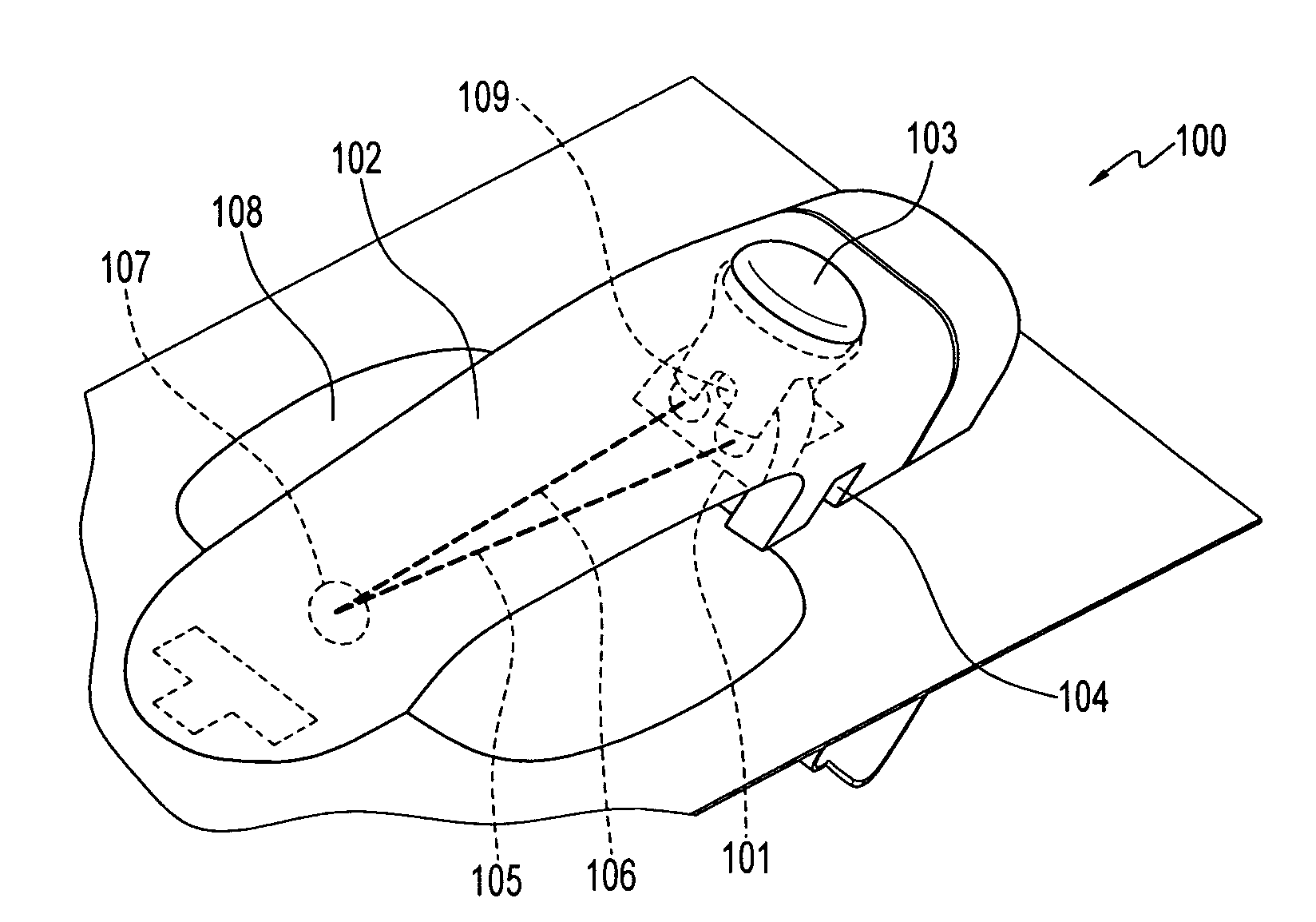
[0038]FIG. 1 of the accompanying drawing illustrates a front perspective view of the passive entry sensor system 100 arranged in a vehicle door handle assembly according to a preferred embodiment. The sensor system includes a sensor 101, a portion of which is mounted in an end of a door handle 102, and a reflector 107, such as a mirror or a flat painted area, located at an opposing end of the handle facing the sensor (all shown in dotted line). The sensor 101 is adapted to transmit an electromagnetic beam of radiation, in this case an IR beam 105, at an angle along the length of the handle to the reflector 107 and to detect the IR beam 106 reflected back by the reflector. The optical sensor 101 is configured to detect an interruption or other...


PUM


Abstract

Passive entry sensor systems and associated sensors are disclosed. The system sensor is locatable in the handle of a door or like structure and can provide an electromagnetic radiation beam transmitted either along the length of the handle between opposite ends thereof or between the handle and the door such that the sensor can detect at least a partial interruption of the beam by a user actuating the handle. The system can include an independent optical locking switch for actuation by a user to lock the door which locking switch comprises a shutter for intercepting the beam so as to flag the sensor. The system can include a power-up switch for actuation by a user to power-up the system, back-up switches for detecting a pull on the handle, indicators for indicating system status to the user, and backlight and ground light lighting.

Description

CROSS-REFERENCE TO PROVISIONAL PATENT APPLICATION [0001] This patent application claims priority under 35 U.S.C. § 119(e) to provisional patent application Ser. No. 60 / 671,943 entitled “Passive Entry Sensor System,” which was filed on Apr. 15, 2005 with the U.S. Patent & Trademark Office, the disclosure of which is incorporated herein by reference.TECHNICAL FIELD [0002] Embodiments are generally related to sensing devices and applications and, in particular, to sensor devices and systems for use in keyless access systems which operate passively to enable access by an authorized user to secured environments. Embodiments are additionally related to multi-functional passive entry sensors and systems. Embodiments are also related to passive entry sensors and system configurations utilized in automotive applications. BACKGROUND OF THE INVENTION [0003] It is important, for many reasons, to control access to premises, vehicles and personal property so that only authorized users are allowed...

Claims


Application Information

Patent Timeline
IPC IPC(8): G05B19/00B60R25/00
CPCE05B81/76E05B81/77H03K17/941G07C9/00309G07C2209/65E05B81/78B60R25/01H03K17/968G07C9/00
Inventor SHELLEY, MICHAEL J.CRAWFORD, ALEXSCHWEIZER, PASCALKETTLE, ADRIANGIERCZAK, MAREK
Owner HONEYWELL INT INC
Why Eureka
Try Eureka