
Method and device for controlling a near eye display

a near eye display and display technology, applied in the field of gesture recognition, can solve the problems of limiting the functional ability to control the presented content, limiting unable to achieve the control of actual touch interfaces, so as to reduce the additional hardware and limit the incremental power consumption

Active Publication Date: 2015-02-12
META PLATFORMS TECH LLC
View PDF6 Cites 42 Cited by
  • Summary
  • Abstract
  • Description
  • Claims
  • Application Information

AI Technical Summary

Benefits of technology

This patent aims to solve issues in previous eyewear devices by using existing components, like the front camera, and a visible light pattern to reduce hardware and power consumption.

Problems solved by technology

Although the information displayed is diverse and may hold various content categories and flexible graphical user interface, there is no convenient and flexible way for controlling the content displayed.
Another aspect that restricts the functional ability to control the presented content is that it is displayed directly to the user's eye.
In this case, actual touch interfaces are not an option for control, creating a need for separating the actual controlling area from the display while maintaining the extended abilities of touch control.
In addition, portable devices, such as near-eye display devices are limited in terms of the acceptable power consumption and weight allowed for the device components.
Therefore, using available gestures capturing technologies, based on an IR illumination source and an additional IR sensor is not practical due to the incremental weight and power consumption.

Method used


Image

  • Method and device for controlling a near eye display
  • Method and device for controlling a near eye display
  • Method and device for controlling a near eye display

Examples


Embodiment Construction

[0024]With specific reference now to the drawings in detail, it is stressed that the particulars shown are by way of example and for purposes of illustrative discussion of the preferred embodiments of the present technique only, and are presented in the cause of providing what is believed to be the most useful and readily understood description of the principles and conceptual aspects of the present technique. In this regard, no attempt is made to show structural details of the present technique in more detail than is necessary for a fundamental understanding of the present technique, the description taken with the drawings making apparent to those skilled in the art how the several forms of the invention may be embodied in practice.

[0025]Before at least one embodiment of the present technique is explained in detail, it is to be understood that the invention is not limited in its application to the details of construction and the arrangement of the components set forth in the follow...


PUM


Abstract

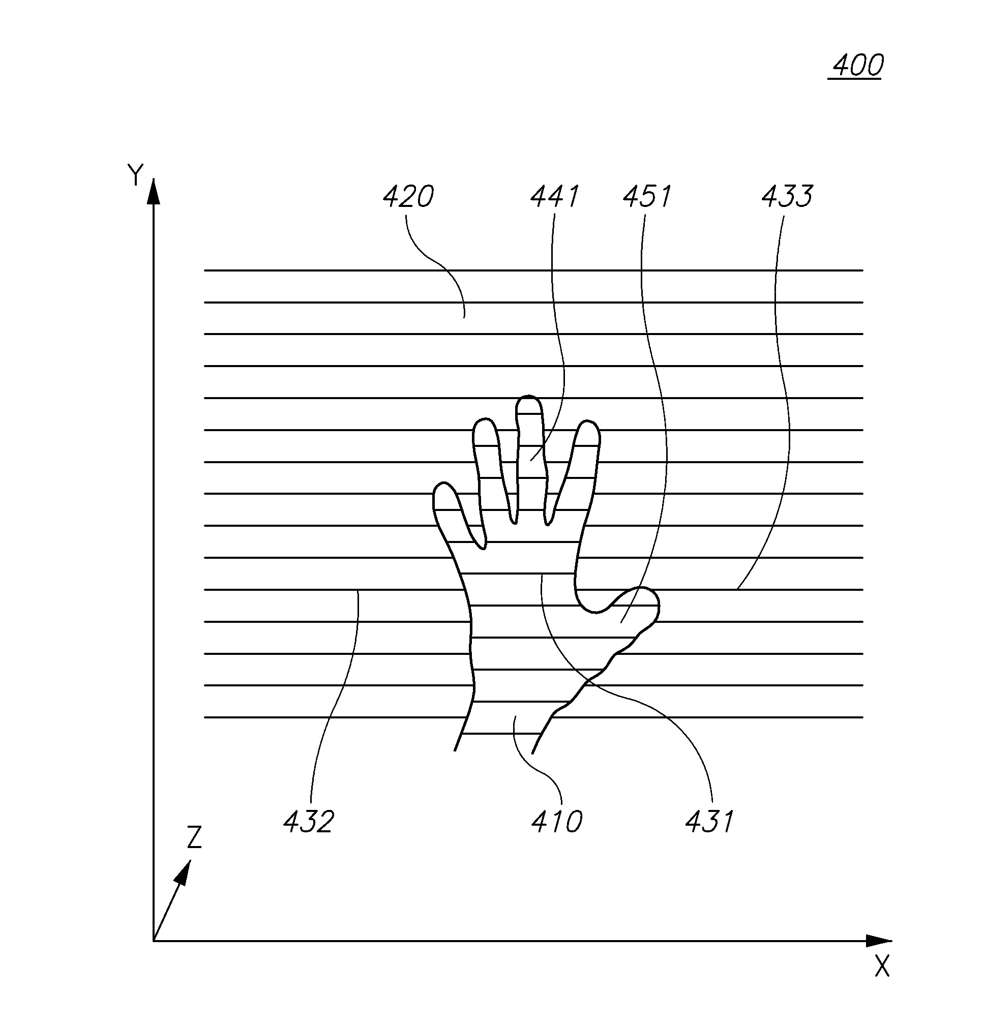
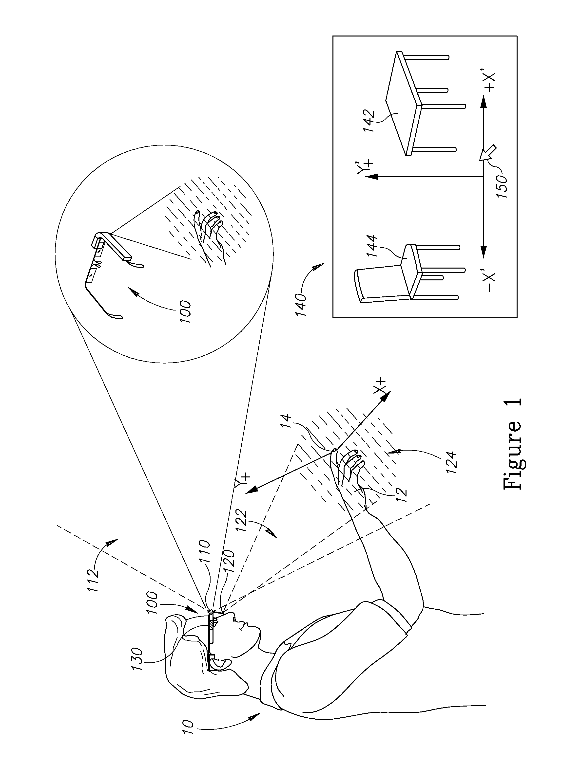
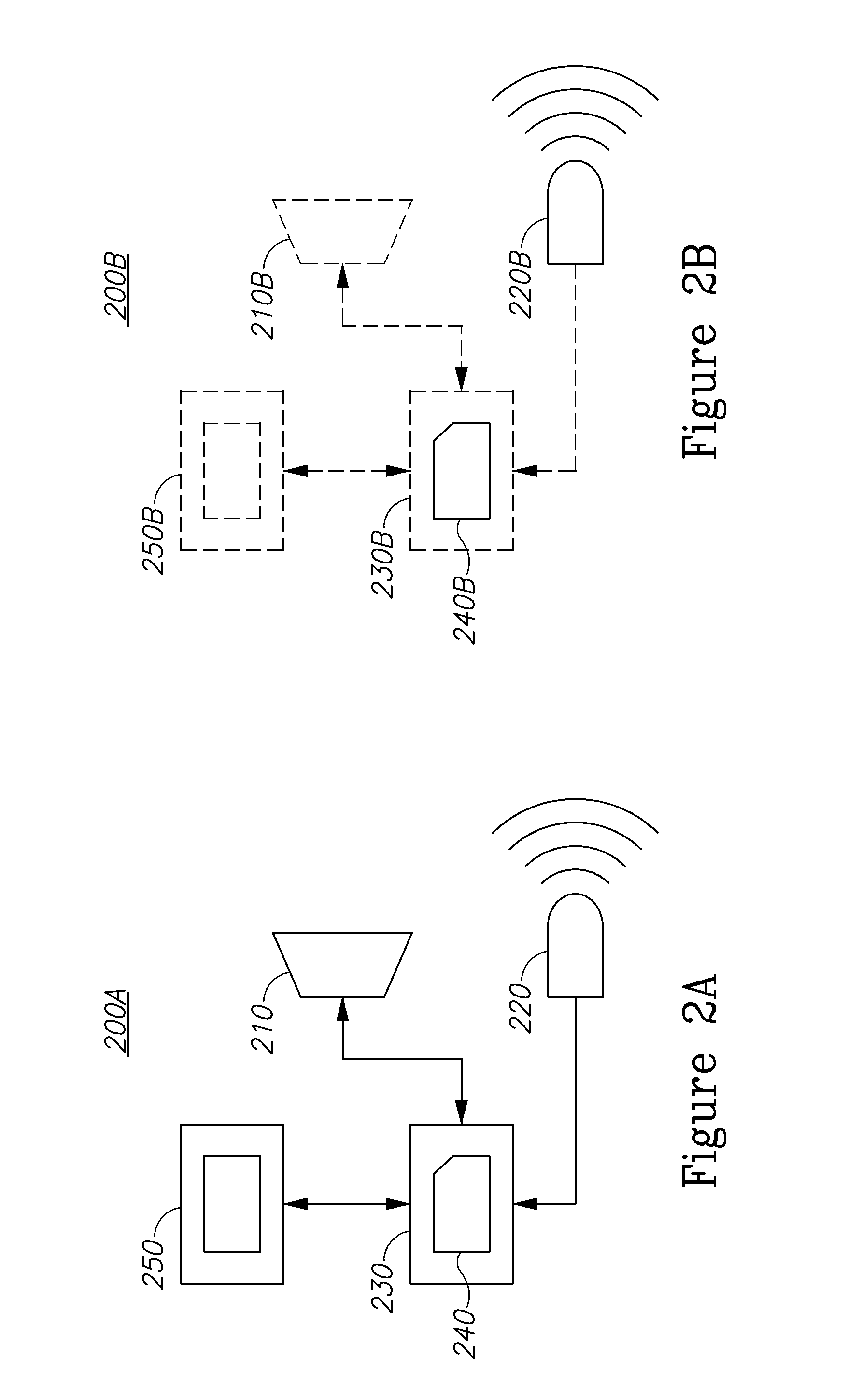
A method and a system for controlling a near eye display using a virtual navigation space are provided herein. The system may include: a wearable near eye display; a sensor having a field of view, attached to the wearable near eye display and configured to capture a scene; a transmitter attached to the wearable near eye display said transmitter is configured to transmit a structured light pattern onto a navigation space, wherein the sensor is configured to capture reflections of the specified pattern coming from the navigation space; and a computer processor configured to analyze said reflections and control a visual indicator presented to a user over the wearable near eye display. The method implements the aforementioned logic without being limited to the architecture.

Description

CROSS-REFERENCE TO RELATED APPLICATIONS[0001]This application claims benefit from U.S. Provisional Patent Application No. 61 / 863,519, filed on Aug. 8, 2013, which is incorporated herein by reference in its entirety.FIELD OF THE INVENTION[0002]The present invention relates generally to the field of gesture recognition, and more specifically, using same for near eye display applications.BACKGROUND OF THE INVENTION[0003]Prior to the background of the invention being set forth, it may be helpful to set forth definitions of certain terms that will be used hereinafter.[0004]The term ‘near eye display’ as used herein is defined as devices which include augmented reality or virtual reality glasses and wearable projected displays.[0005]The term ‘field of view’ as used herein is defined as the extent of the observable world that is seen at any given moment by a user or a sensor.[0006]The term ‘Augmented Reality’ (AR) as used herein is defined as a live direct or indirect view of a physical, r...

Claims


Application Information

Patent Timeline
IPC IPC(8): G06T19/00G09G3/34
CPCG06T19/006G09G2360/14G06T2219/008G09G3/3406G06F1/163G06F3/011G06F3/017G06F3/0304
Inventor GROSSINGER, NADAVALPEM, YAIR
Owner META PLATFORMS TECH LLC
Learn More