
Phosphorescent iridium complexes

a technology of phosphorescent iridium complexes and complexes, which is applied in the direction of discharge tube luminescnet screens, natural mineral layered products, etc., can solve the problems of large loss of efficiency and performance limitations, and hinder many desirable applications

Active Publication Date: 2006-10-12
GLOBAL OLED TECH
View PDF5 Cites 28 Cited by
  • Summary
  • Abstract
  • Description
  • Claims
  • Application Information

AI Technical Summary

Benefits of technology

[0015] The organometallic compounds will provide desirable light emission...

Problems solved by technology

While organic electroluminescent (EL) devices have been known for over two decades, their performance limitations have represented a barrier to many desirable applications.
However, it is generally believed that only 25% of the excitons created in an EL device are singlet excitons.
This results in a large loss in efficiency since 75% of the available excitons are not used in the light emission process.

Method used


Image

  • Phosphorescent iridium complexes
  • Phosphorescent iridium complexes
  • Phosphorescent iridium complexes

Examples


example 1

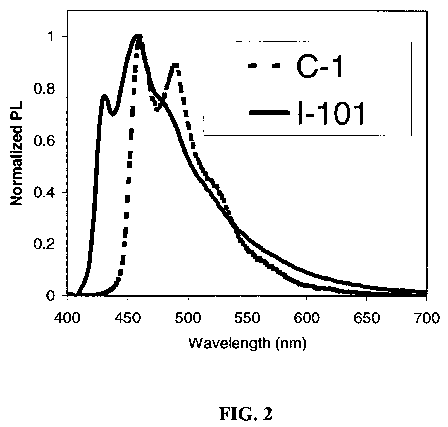
Synthesis of Transition Metal Complex I-101

Step 1

[0105] 2-(2′,4′-difluorophenyl)pyrazole (3.6 g, 20 mmol) and K3IrBr6 (6.3 g, 8 mmol) were added to a flask containing 90 ml 2-ethoxyethanol and 30 ml water. The reaction mixture was heated to reflux and stirred under a nitrogen atmosphere for 24 h. After cooling, the pale yellow precipitate was vacuum filtered and washed first with ethanol followed by heptanes. The product [2-(4′,6′-diflouorophenyl)pyrazole]2Ir2(μ-Br)2[2-(4′,6′-diflouorophenyl)pyrazole]2 was dried in vacuum oven (4.2 g, 81%).

Step 2

[0106] To a 60 ml THF suspension of potassium t-butoxide (7.9 g, 59 mmol) and 2-acetylpyridine(7.1 g, 59 mmol) was added dropwise ethyl trifluoroacetate (10 g, 70 mmol) at 10° C., and the mixture was stirred at room temperature for 15 h. After the PH value of the mixture had been adjusted to 6-7 with 10% H2SO4, the solution was extracted with Et2O. The organic layer was dried (MgSO4) and evaporated. The residue was purified by column c...

example 2

Synthesis of Transition Metal Complex C-1 (Comparison)

Step 1

[0110] 2-(2′,4′-difluorophenyl)pyridine (3.6 g, 19 mmol) and K3IrBr6 (6.3 g, 8 mmol) were added to a flask containing 90 ml 2-ethoxyethanol and 30 ml water. The reaction mixture was heated to reflux and stirred under an nitrogen atmosphere for 24 h. After cooling, the pale yellow precipitate was vacuum filtered and washed first with ethanol followed by heptanes. The product [2-(4′,6′-diflouorophenyl)pyridine]2Ir2(μ-Br)2[2-(4′,6′-diflouorophenyl)pyridine]2 was dried in vacuum oven (3.9 g, 78%).

Step 2

[0111] [2-(4′,6′-difluorophenyl)pyridine]2Ir2(μ-Br)2[2-(4′,6′-difluorophenyl)pyridine]2 (0.15 g, 0.12 mmol), 3-(pyridine-2-yl)-5-trifluoromethylpyrazole (70 mg, 0.3 mmol) and 0.2 g of K2CO3 were refluxed under an nitrogen atmosphere in 2-ethoxyethanol for 18 h. After cooling to room temperature, water was added and a white precipitate was filtered and washed with water. The crude product was chromatographed on a silicon col...


PUM

PropertyMeasurementUnit
Energyaaaaaaaaaa
Energyaaaaaaaaaa
Energyaaaaaaaaaa

Abstract

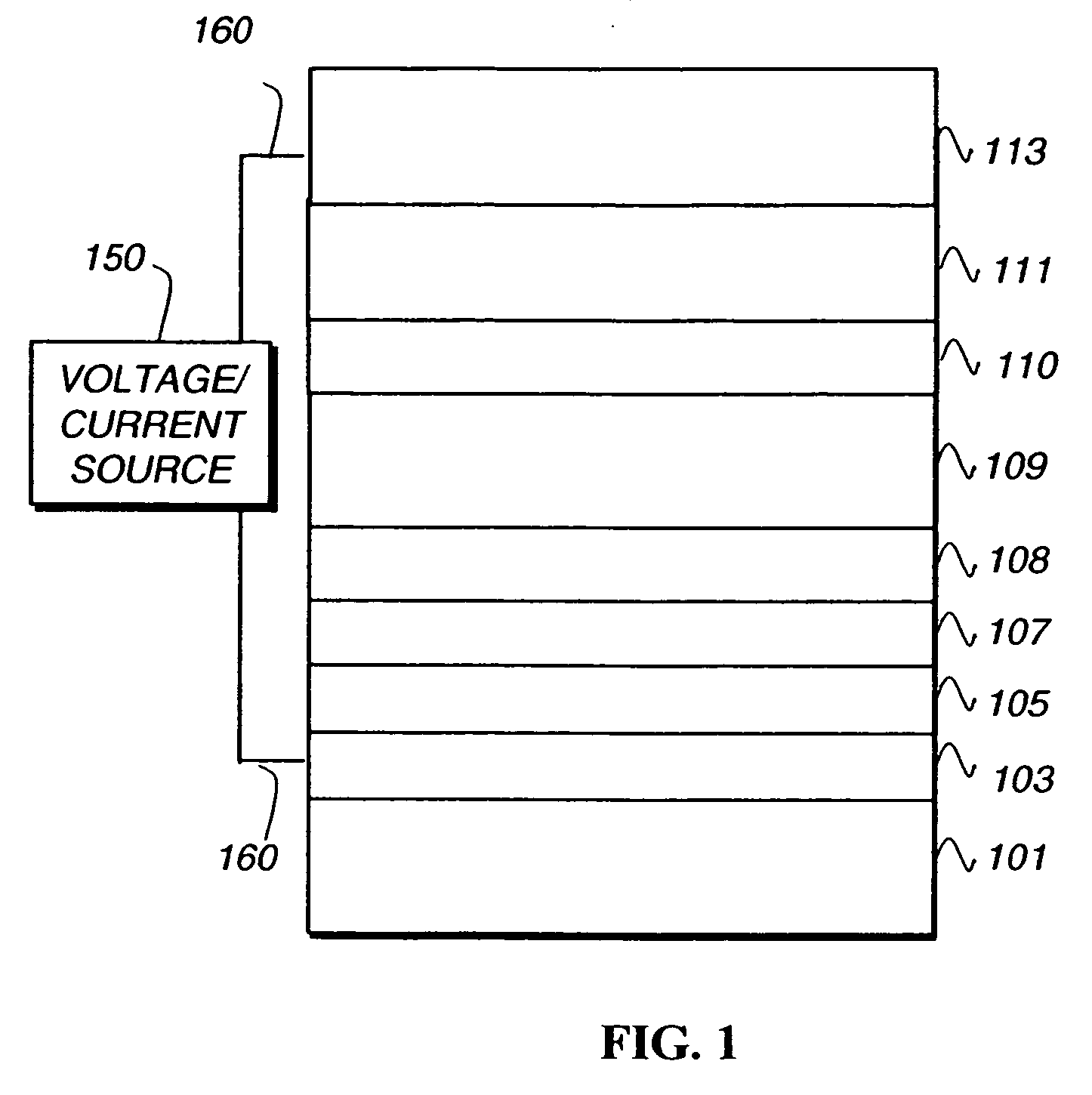
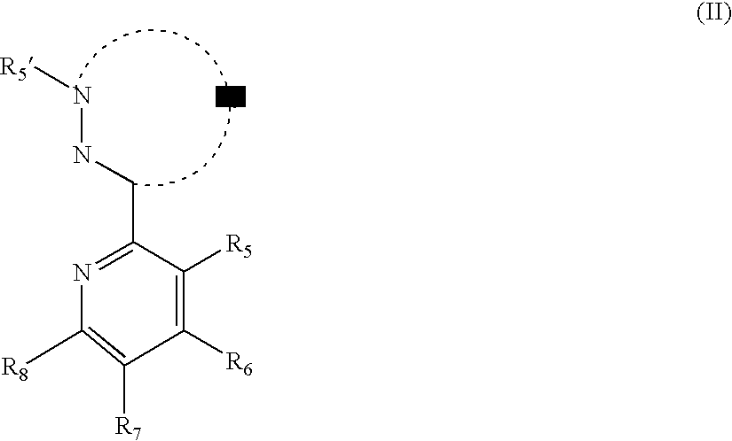
An OLED device comprises a cathode, an anode, and located therebetween a light emitting layer containing a compound represented by formula (I): Am-M-Bn  (I) wherein m+n=2 or 3 and neither m nor n is 0; M is Ir, Pt, Os, Ru, Rh, or Pd; Am includes at least one ligand A having a triplet energy of at least 2.9 eV as measured in a homoleptic complex of M and A; and B is represented by the formula (II): wherein Q represents an atomic group forming a nitrogen-containing heterocyclic ring; and R5, R6, R7, R8 and R5′ independently represent a hydrogen atom or a substituent.

Description

FIELD OF INVENTION [0001] This invention relates to organic electroluminescent diode OLED) devices containing iridium complexes capable of triplet emissions in the deep blue spectral range. BACKGROUND OF THE INVENTION [0002] While organic electroluminescent (EL) devices have been known for over two decades, their performance limitations have represented a barrier to many desirable applications. In simplest form, an organic EL device is comprised of an anode for hole injection, a cathode for electron injection, and an organic medium sandwiched between these electrodes to support charge recombination that yields emission of light. These devices are also commonly referred to as organic light-emitting diodes, or OLEDs. Representative of earlier organic EL devices are Gurnee et al. U.S. Pat. No. 3,172,862, issued Mar. 9, 1965; Gurnee U.S. Pat. No. 3,173,050, issued Mar. 9, 1965; Dresner, “Double Injection Electroluminescence in Anthracene”, RCA Review, Vol. 30, pp. 322-334, 1969; and Dre...

Claims


Application Information

Patent Timeline
IPC IPC(8): H01L51/54H05B33/14
CPCC09K11/06C09K2211/1029C09K2211/1044H05B33/14H01L51/0085H01L51/5016C09K2211/185Y10S428/917H10K85/342H10K50/11H10K2101/10
Inventor REN, XIAOFANDEATON, JOSEPH C.
Owner GLOBAL OLED TECH
Learn More