
Technique for detecting microorganisms

a microorganism and detection technology, applied in the field of microorganism detection, can solve the problems of increasing the difficulty of rapid detection of microorganisms, increasing the difficulty of detecting microorganisms, and increasing the number of undesirable levels of microorganisms,

Inactive Publication Date: 2006-10-05
KIMBERLY-CLARK WORLDWIDE INC
View PDF44 Cites 103 Cited by
  • Summary
  • Abstract
  • Description
  • Claims
  • Application Information

AI Technical Summary

Benefits of technology

"The present invention provides a method for detecting the presence of microorganisms by extracting a headspace gas produced by a culture of the microorganism and identifying a volatile compound associated with the microorganism culture. An indicator is selected that is capable of undergoing a detectable color change in the presence of the identified volatile compound. The invention also provides a substrate for detecting the presence of multiple microorganisms, which contains at least first and second indicator zones, with a first indicator contained within the first indicator zone in an amount effective to cause a detectable color change upon contact with a first volatile compound produced by a first microorganism and a second indicator contained within the second indicator zone in an amount effective to cause a detectable color change upon contact with a second volatile compound produced by a second microorganism."

Problems solved by technology

The ability to rapidly detect microorganisms is becoming an increasing problem in a wide variety of industries.
However, no further testing generally occurs before the food product is consumed, leaving the possibility that undetected food-borne pathogens, such as Salmonella and Listeria, will multiply to an undesirable level during the packaging, transportation, and display of the product.
For instance, a temperature increase of less than 3° C. may shorten food shelf life by 50% and cause a significant increase in bacterial growth over time.
To date, none of these devices have been widely accepted due to the technology applied.
If the bacteria are internal to the exterior food surface, however, then an internally high bacterial load on the food does not activate the sensor.
Ammonia sensors have also been developed, but are only able to detect bacteria that break down proteins.
Because bacteria initially utilize carbohydrates, these sensors have a low sensitivity in many applications.
Unfortunately, such pH indicators are still problematic.
The lowered pH does not, however, provide an indication regarding what type of bacteria is present.

Method used


Image

  • Technique for detecting microorganisms
  • Technique for detecting microorganisms
  • Technique for detecting microorganisms

Examples


example 1

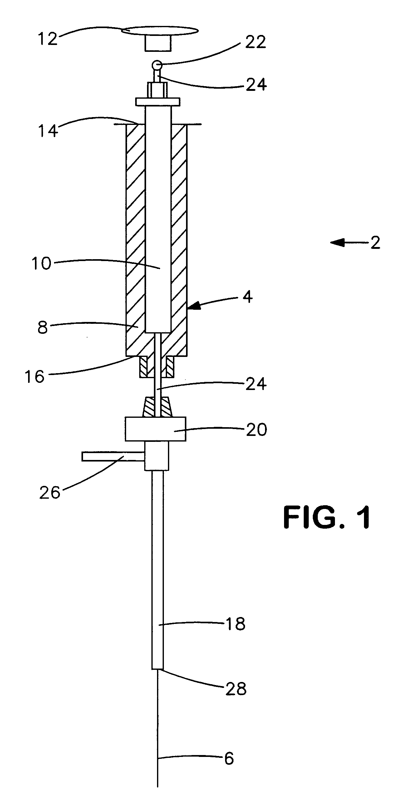
[0056] The ability to identify one or more volatile compounds associated with a particular type of bacteria was demonstrated. In this particular example, P. aeruginosa (ATCC #9027) was tested. A suspension of P. aeruginosa was prepared by diluting a 1×10⁸ colony forming unit (cfu) per milliliter (ml) stock of the microorganism with a tryticase soy broth (“TSB”) solution to a concentration of 1×10⁵ cfu / ml. One milliliter of the suspension was applied to Dextrose Sabouraud agar plates, and allowed to grow at 35° C. for 4 hours. A sample was prepared by placing the P. aeruginosa suspension into 250-milliliter septa-jar and sealing it with an aluminum foil-lined Teflon / silicone cap. For control purposes, a nutrient blank was also prepared.

[0057] The test and control samples were exposed to a 85-micrometer Carboxen™ / polydimethylsilicone “Solid Phase Microextraction” (SPME) assembly for about 30 minutes to collect the volatiles for analysis. (Supelco catalog No. 57330-U manual fiber hold...

example 2

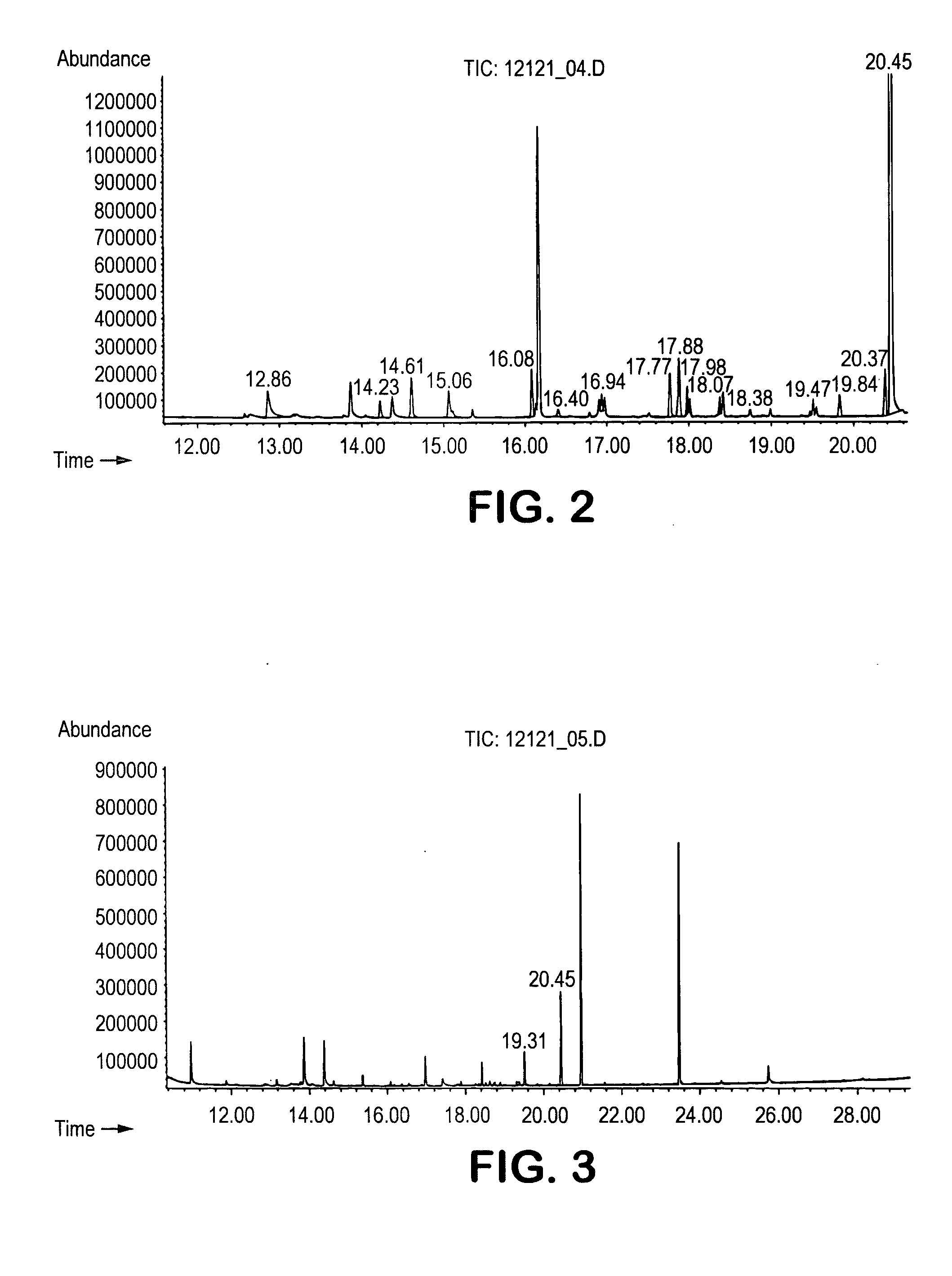
[0061] The procedure of Example 1 was utilized to identify volatile compounds produced by S. aureus (ATCC #6538). The acquired total ion chromatogram for S. aureus is set forth in FIG. 3. The peaks of the spectrum were matched to a corresponding compound using the mass-to-charge ratios in the spectrum and their relative abundance. Only two compounds exhibited a peak substantially greater in concentration than the nutrient blank. These two compounds are identified below in Table 4.

TABLE 4Spectral Analysis for S. aureusTimeCAS No.Compound19.3124295-03-22-acetylthiazole20.44821-95-41-undecene

[0062] As indicated, the volatile compounds identified as being associated with S. Aureus included a thiazole and alkene.

example 3

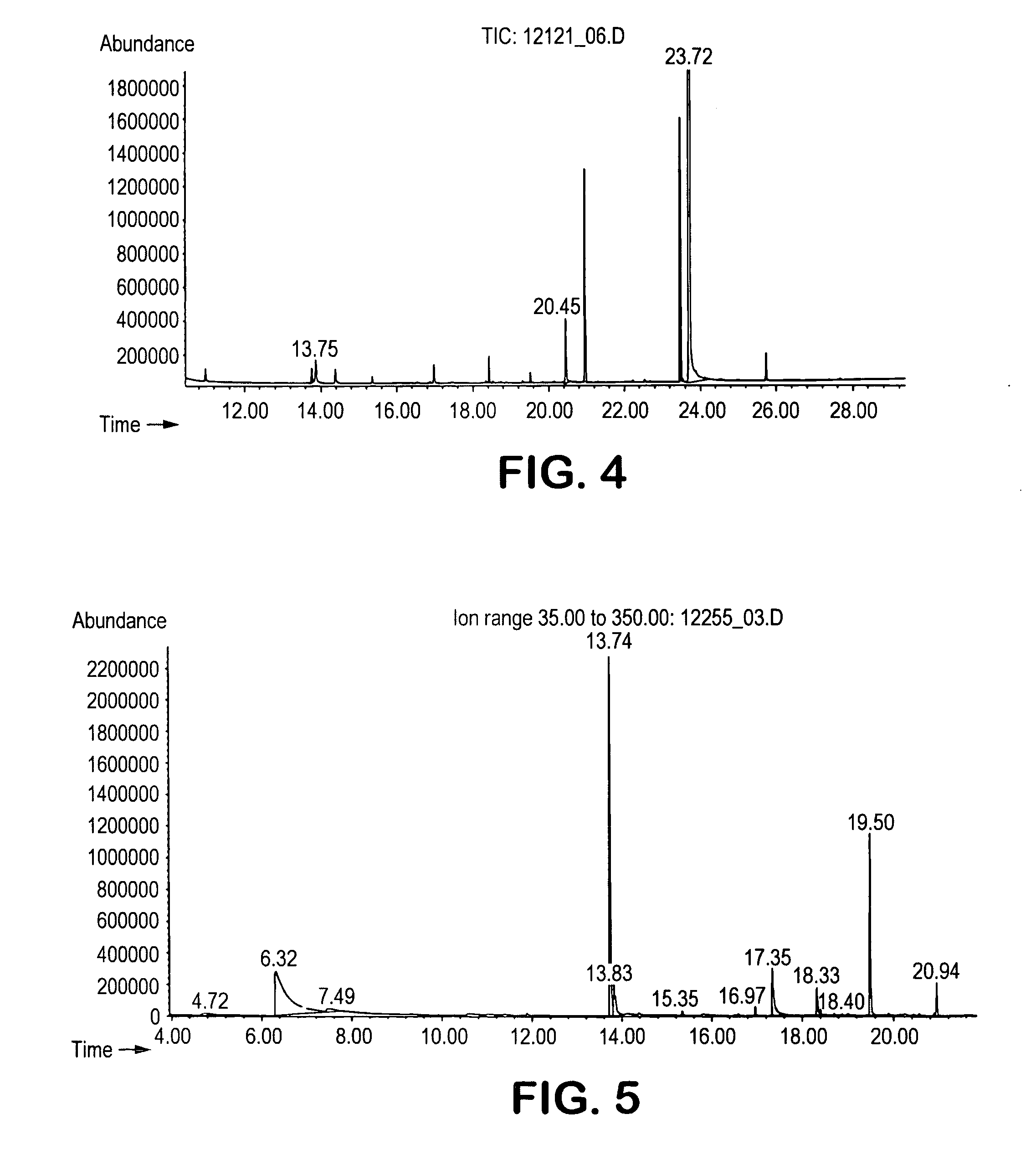
[0063] The procedure of Example 1 was utilized to identify volatile compounds produced by E. coli (ATCC #8739). The acquired total ion chromatogram for E. coli is set forth in FIG. 4. The peaks of the spectrum were matched to a corresponding compound using the mass-to-charge ratios in the spectrum and their relative abundance. Only three compounds exhibited a peak substantially greater in concentration than the nutrient blank. These three compounds are identified below in Table 5.

TABLE 5Spectral Analysis for E. coliTimeCAS No.Compound13.75123-51-33-methyl-1-butanol20.44821-95-41-undecene23.72120-72-9indole

[0064] As indicated, the volatile compounds identified as being associated with E. coli included an alcohol, alkene, and fused heterocyclic compound.


PUM

PropertyMeasurementUnit
temperatureaaaaaaaaaa

Abstract

A technique for detecting the presence of microorganisms in a simple, rapid, and efficient manner is provided. More specifically, the technique involves identifying one or more volatile compounds associated with a particular microorganism of interest. The volatile compounds may be identified, for instance, using solid phase microextraction in conjunction with gas chromatography / mass spectroscopy (“GC / MS”) analysis methods. Once identified, an indicator may then be selected that is configured to undergo a detectable color change in the presence of the identified volatile compound(s). If desired, the indicator may be provided on a substrate to form an indicator strip for use in a wide variety of applications. In this manner, the presence of the microorganism may be rapidly detected by simply observing a color change of the indicator strip.

Description

BACKGROUND OF THE INVENTION [0001] The ability to rapidly detect microorganisms is becoming an increasing problem in a wide variety of industries. For instance, food products (e.g., meat) are normally analyzed before, during, or after entry into an establishment. However, no further testing generally occurs before the food product is consumed, leaving the possibility that undetected food-borne pathogens, such as Salmonella and Listeria, will multiply to an undesirable level during the packaging, transportation, and display of the product. For instance, a temperature increase of less than 3° C. may shorten food shelf life by 50% and cause a significant increase in bacterial growth over time. Indeed, spoilage of food may occur in as little as several hours at 37° C. based on a total pathogenic and non-pathogenic bacterial load of 103 colony forming units (“cfu”) per gram on food products. Food safety leaders have identified this level as the maximum acceptable threshold for meat produ...

Claims


Application Information

Patent Timeline
Patent Type & Authority Applications(United States)
IPC IPC(8): C12Q1/70C12Q1/04
CPCG01N33/523C12Q1/04
Inventor MACDONALD, JOHN GAVINBORDERS, RICHARD A.
Owner KIMBERLY-CLARK WORLDWIDE INC
Learn More