
System and method for X-ray generation

a generation system and x-ray technology, applied in the direction of radioactive sources, electrical discharge tubes, electrical equipment, etc., can solve the problems of large and expensive facilities, large overall size of these systems, and inability to reduce to practice easily,

Inactive Publication Date: 2006-10-05
GENERAL ELECTRIC CO
View PDF15 Cites 26 Cited by
  • Summary
  • Abstract
  • Description
  • Claims
  • Application Information

AI Technical Summary

Benefits of technology

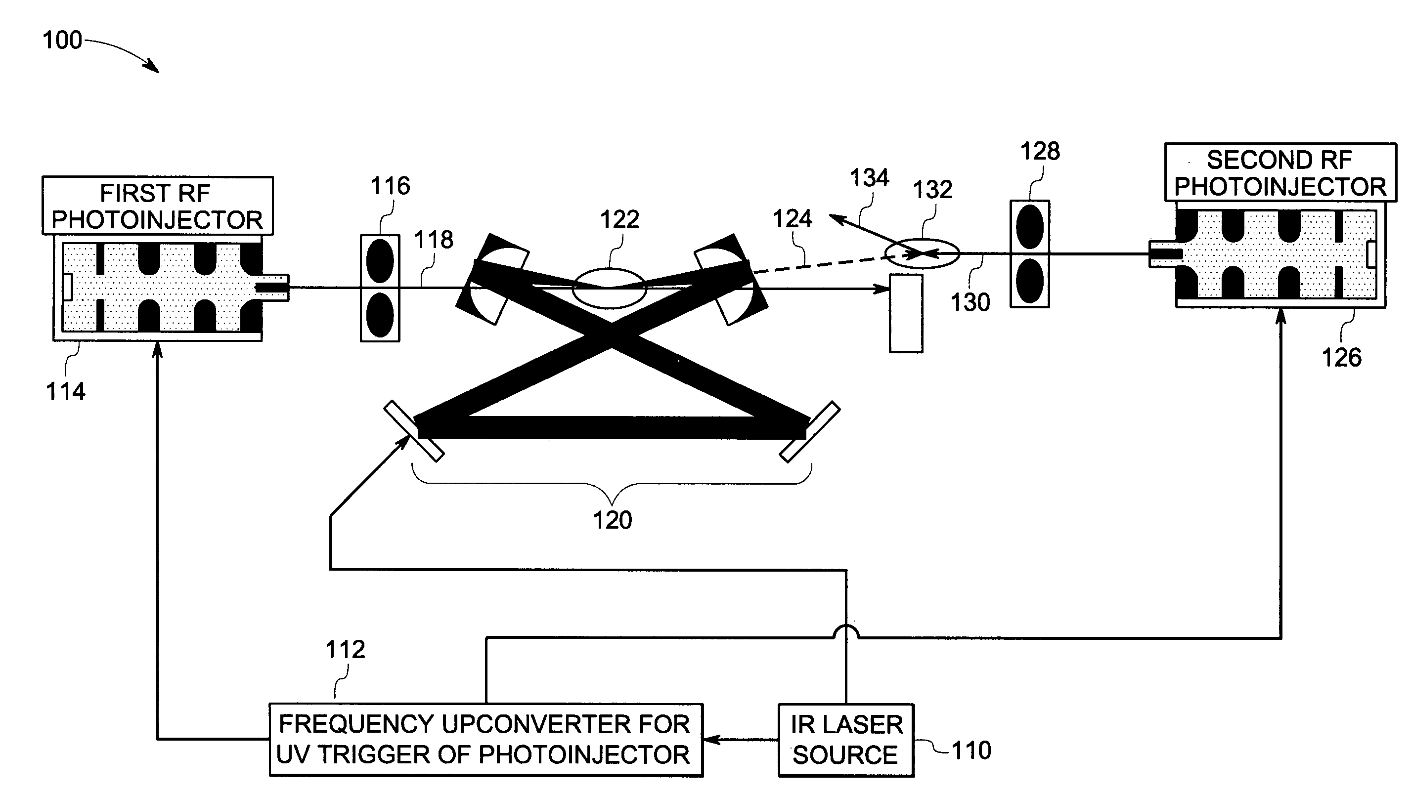
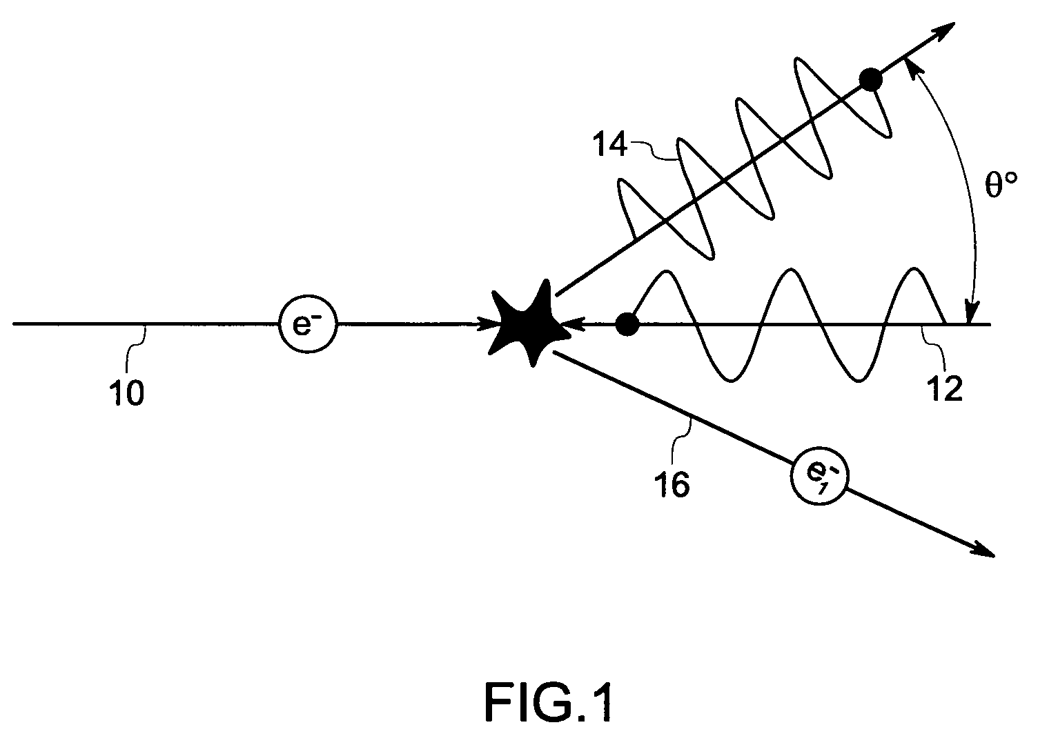
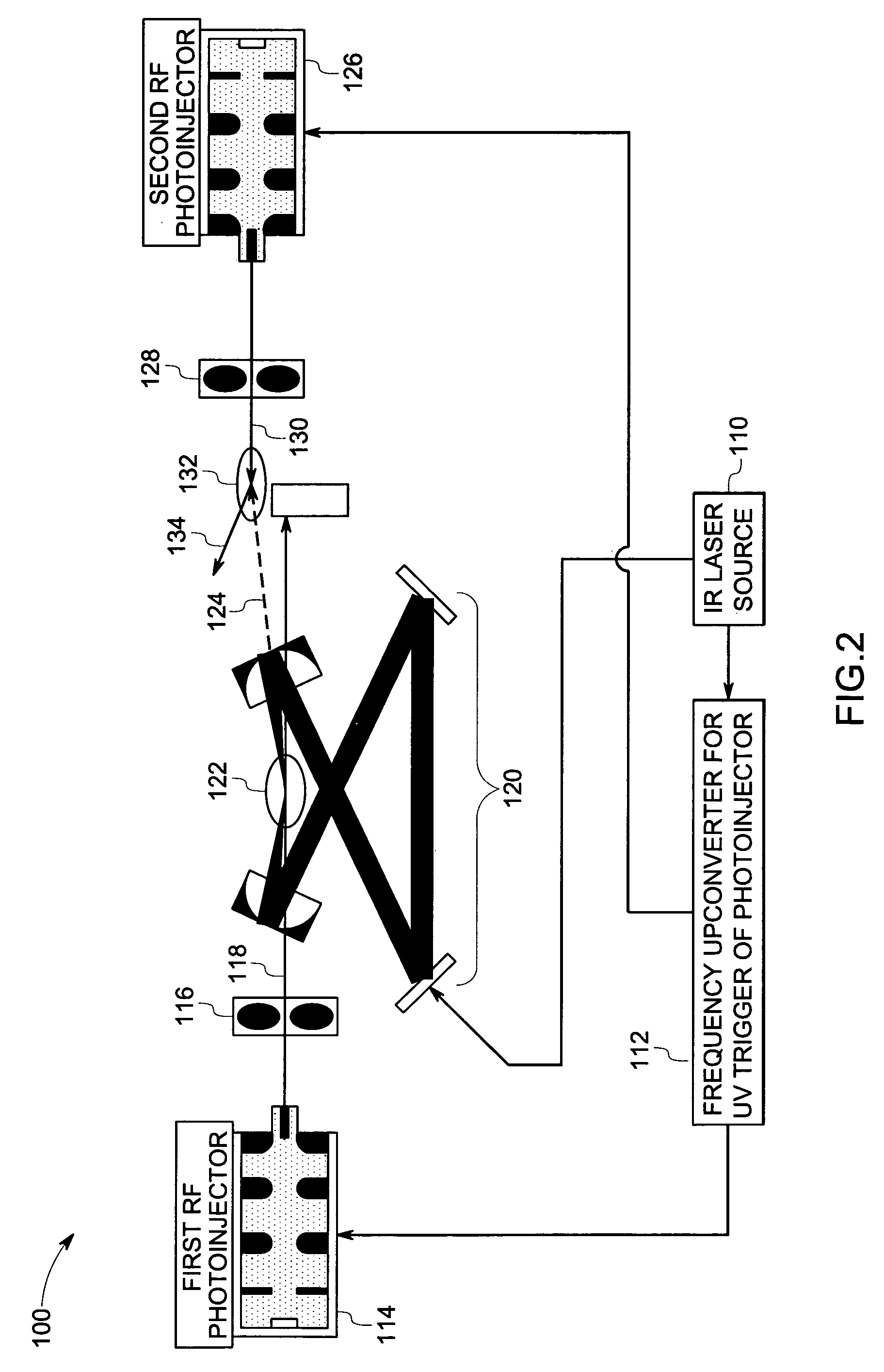
"The patent describes an inverse Compton scattering system for generating an X-ray pulse with a tunable energy. The system includes a laser beam source and a first electron beam source that interact with a first photon pulse to produce a second photon pulse with higher energy. A second electron beam source then interacts with the second photon pulse to produce a tunable X-ray pulse with a specific energy and duration. The system can be used in an imaging system to produce high-quality X-ray images. The technical effect of the patent is to provide a reliable and efficient method for generating X-ray pulses with adjustable energy and duration."

Problems solved by technology

Moreover, such radiation is randomly polarized, incoherent radiation with a broad range of energies that is not easily energy selectable or energy tunable.
In addition, such sources require high energetic electron beams, which in turn require large and expensive facilities.
Although tunable, mono-energetic inverse Compton scattering X-ray systems sources have been constructed and demonstrated, the major drawback to these systems is their overall size, often encompassing several large rooms.
While such designs work in theory, they do not reduce to practice easily due to reliability issues associated with the very high electric fields.

Method used


Image

  • System and method for X-ray generation
  • System and method for X-ray generation
  • System and method for X-ray generation

Examples


example 1

[0039] In one example, a laser source lasing at 1 micron pumps an optical resonator which comprises an interaction chamber through which a 3 MeV electron beam passes. The photons in the laser beam are inverse Compton scattered to produce photons at about 7.2 nm wavelength. The 7.2 nm photons are then directed towards a second interaction chamber where they scatter off another 3 MeV electron beam. As a result of this second ICS process, the photons gain additional energy resulting in hard X-rays with energy of about 24 keV.

example 2

[0040] In another example, a laser source lasing at 1 micron pumps an optical resonator which comprises an interaction chamber through which a 4 MeV electron beam passes. The photons in the laser beam are inverse Compton scattered to produce photons at about 4 nm wavelength. The 4 nm photons are then directed towards a second interaction chamber where they scatter off another 2 MeV electron beam. As a result of this second ICS process, the photons gain additional energy resulting in hard X-rays with energy of about 10 keV.

[0041] The previously described embodiments of the present invention have many advantages, especially the elimination of the large electron accelerator modules. This enables the use of lower energy electrons available directly from RF photoinjector sources, which can be built of modest size, even less than one-half meter, allowing for a compact tube-like structured cascaded ICS X-ray generation system.


PUM


Abstract

A system for generating a tunable X-ray pulse comprises a first electron beam source configured to direct a first electron pulse of predetermined energy and pulse length towards a first interaction zone, a laser beam source configured to direct a first photon pulse of predetermined energy and pulse length towards the first interaction zone to interact with the first electron pulse. The first interaction produces a substantially monochromatic second photon pulse of higher photon energy directed towards a second interaction zone, and a second electron beam source configured to direct a second electron pulse of predetermined energy and pulse length towards the second interaction zone so that the second interaction produces an X-ray pulse of predetermined energy and pulse length in a cascaded inverse Compton scattering (ICS) configuration.

Description

BACKGROUND [0001] The invention relates generally to X-ray generation systems. The invention particularly relates to inverse Compton scattering X-ray generation systems. [0002] Conventional X-ray sources generally rely on either Bremsstrahlung radiation or synchrotron radiation. In Bremsstrahlung radiation X-ray embodiments, radiation is produced when energetic electrons are decelerated by heavy solid targets made of dense, high-Z materials. For example, radiation in common medical diagnostic X-ray tubes is generally of relatively low power and comprises long pulses or a continuous wave radiation. Moreover, such radiation is randomly polarized, incoherent radiation with a broad range of energies that is not easily energy selectable or energy tunable. Where synchrotron radiation is desired, radiation is produced by ultrahigh energy electron beams passing through magnetic undulators or dipoles in a storage ring synchrotron source. The X-rays generated by the synchrotron source are gen...

Claims


Application Information

Patent Timeline
Patent Type & Authority Applications(United States)
IPC IPC(8): H05G2/00G21G4/00H01J35/00
CPCH05G2/00
Inventor FILKINS, ROBERT JOHNPRICE, JOHN SCOTTLAWRENCE, BRIAN LEENIELSEN, MATTHEW CHRISTIANMANAK, JOSEPH JOHNDUNHAM, BRUCE MATTHEW
Owner GENERAL ELECTRIC CO
Learn More