Concrete cask and method for manufacturing thereof

a technology of concrete casks and casks, which is applied in the field of concrete casks, can solve the problems of stress corrosion cracking, concrete cask corrosion, and unavoidable introduction of sea salt particles from outside air into the concrete cask,

Inactive Publication Date: 2006-10-05
KOBE STEEL LTD +1
View PDF8 Cites 18 Cited by
  • Summary
  • Abstract
  • Description
  • Claims
  • Application Information

AI Technical Summary

Benefits of technology

[0010] In order to solve the above mentioned problems according to the present invention, a concrete cask in which a shielding body composed of concrete and heat transfer fins made from metal are provided between an inner shell and an outer shell made from metal and which comprises an accommodation portion formed inside the inner shell for accommodating a radioactive substance, a containment structure is employed to shield the accommodation portion from the outside of the cask, and in the heat transfer fins, the portions thereof at the inner shell-side are provided in contact with the inner shell and the portions thereof at the outer shell-side are cut so as to form a separation portion with respect to the outer shell, or the portions thereof at the outer shell-side are provided in contact with the outer shell and the portions thereof at the inner shell-side are cut so as to form a separation portion with respect to the inner shell.

Problems solved by technology

In this case, corrosion-inducing substances such as sea salt particles contained in the outside air are unavoidably introduced into the concrete cask and adhere to the canister surface.
As a result the canister surface is corroded and sometimes stress corrosion cracking can occur under the combined effect with the residual stresses present in the vicinity of welds in the canister.
Such cracking means that the containment of canister is disrupted and radioactive material can be emitted to the outside.
Furthermore, because the above-mentioned openings serving as the inlet and outlet were the portions that were not covered with a shielding body (portions that lack shielding), radiation streaming from those openings could not be avoided.
Therefore, the problem was that no shielding body was present in the heat transfer fin portions and radiation penetrated through the heat transfer fins and streamed in the radial direction.
In this case the manufacture was a time-consuming operation.

Method used


Image

  • Concrete cask and method for manufacturing thereof
  • Concrete cask and method for manufacturing thereof
  • Concrete cask and method for manufacturing thereof

Examples


first embodiment

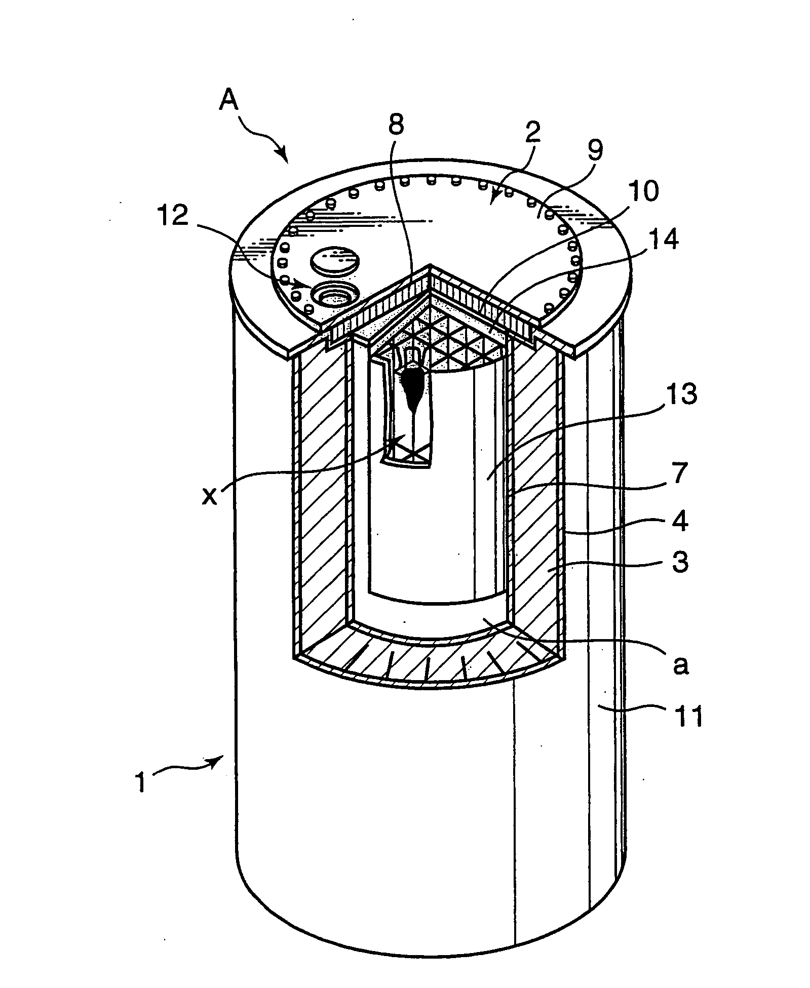
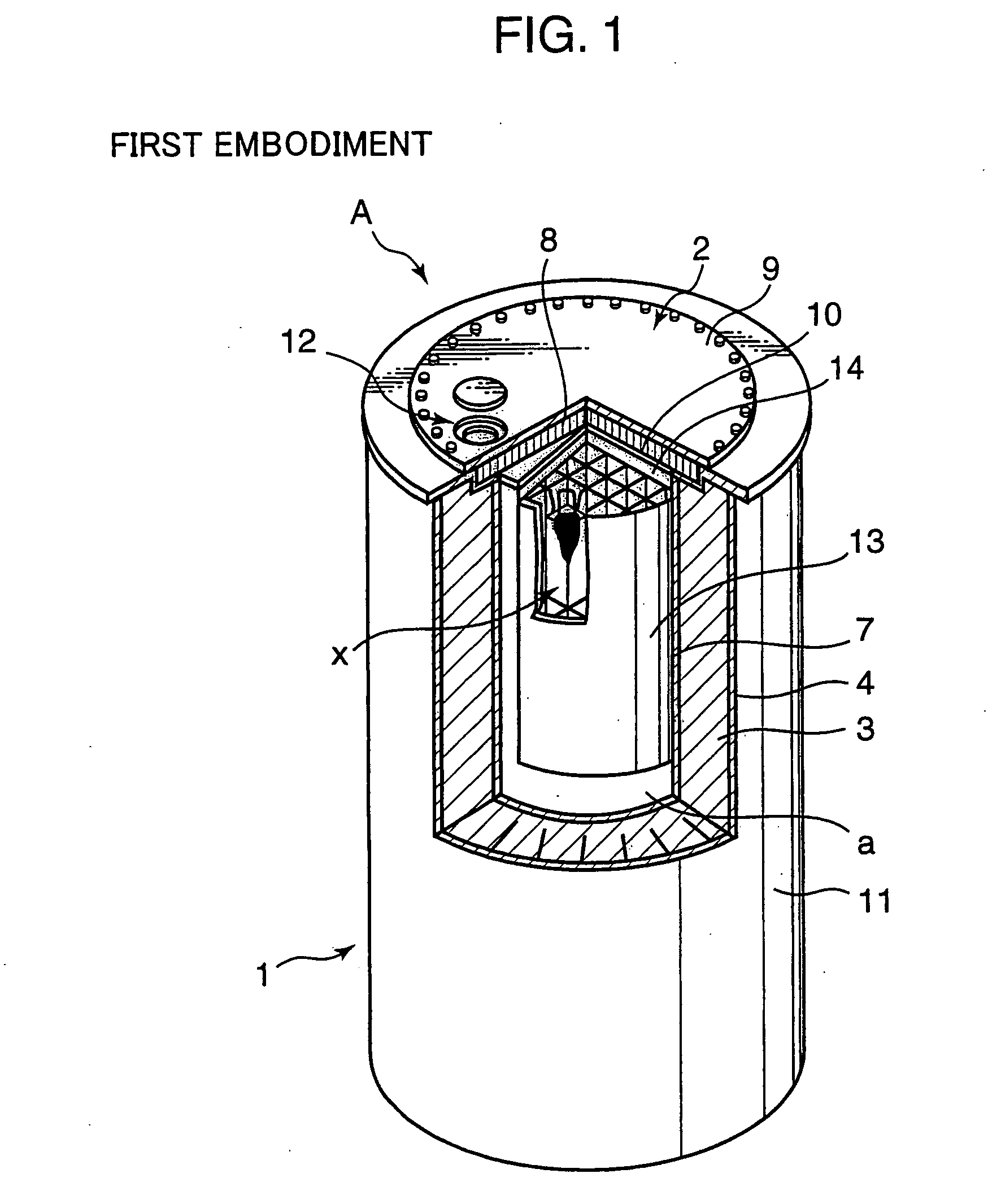
[0036] The concrete cask A of the first embodiment shown in FIG. 1 and FIG. 2 is composed of a tubular container body 1 open at both ends. A canister (a) is provided inside the concrete cask A.

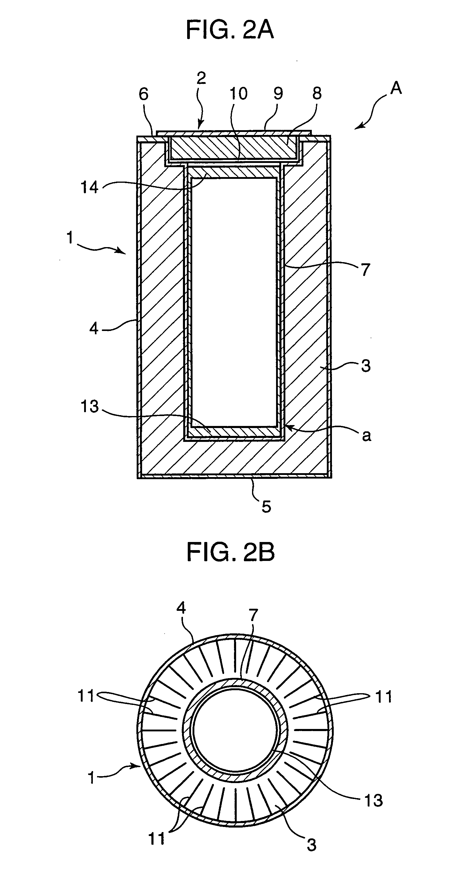
[0037] The container body 1 has a structure in which a concrete container 3 is covered with an outer shell 4 made from carbon steel, a bottom cover 5 made from carbon steel, a thick flange made from carbon steel, and an inner shell 7 made from carbon steel. An accommodation portion for accommodating the canister (a) is constructed inside the inner shell 7 (inside the container body 1). A lid 2 has a structure in which a concrete lid member 8 is covered with a thick upper lid 9 made from carbon steel and a lower cover 10 made from carbon steel. Multiple heat transfer fins 11 made from copper, carbon steel, or aluminum alloy are embedded and installed in the container 3 so as to be connected to the inner wall of the outer shell 4, as shown in FIG. 1 or FIG. 2B.

[0038] The heat transfer fins are ...

third embodiment

[0048] In the third embodiment illustrated by a lateral sectional view in FIG. 4, the end portions of the heat transfer fins 18 at the side of the outer shell 4 are connected to the inner wall of the outer shell 4, whereas the end portions at the side of the inner shell 7 (ends that form a separation portion with respect to the inner shell 7) are bent at an almost right angle along the appropriate width to obtain an L-like shape. As a result, the portions that were bent (bent portions) form opposite surfaces that face the outer wall of the inner surface 7 at an appropriate distance therefrom (separation portion).

fourth embodiment

[0049] In the fourth embodiment illustrated by a lateral sectional view in FIG. 5, the end portions of the heat transfer fins 18′ at the side of the inner shell 7 are connected to the outer wall of the inner shell 7, whereas the end portions at the side of the outer shell 4 (ends that form a separation portion with respect to the outer shell 4) are bent at an almost right angle along the appropriate width to obtain an L-like shape. As a result, the portions that were bent (bent portions) form opposite surfaces that face the inner wall of the outer shell 4 at an appropriate distance therefrom (separation portion).

[0050] In the above-described third and fourth embodiments, the heat transfer fins 18, 18′ have such bent portions. Therefore, a large surface area of the surfaces (opposite surfaces) of the heat transfer fins 18, 18′ that face the inner shell 7 or outer shell 4 can be ensured. As a result, heat transfer can be enhanced and a concrete cask A with excellent cooling capacity c...


PUM


Abstract

It is an object of the present invention to obtain a containment concrete cask which has heat removal capacity maintained at the conventional level or beyond it and which prevents radiation from leaking to the outside. In a concrete cask, a shielding body composed of concrete and heat transfer fins made from metal are provided between an inner shell and an outer shell made from metal, and an accommodation portion for accommodating a radioactive substance is provided inside the inner shell. The accommodation portion has a containment structure to be insulated from the outside of the cask. In the heat transfer fins, the portions thereof at the outer shellside are provided in contact with the outer shell and the portions thereof at the inner shell side are cut so as to form a separation portion with respect to the inner shell.

Description

BACKGROUND OF THE INVENTION [0001] 1. Field of the Invention [0002] The present invention relates to a concrete cask suitable for the transportation or long-term storage of radioactive material such as spent nuclear fuels. [0003] 2. Description of the Related Art [0004] Concrete casks described in Japanese Patent Applications Laid-open No. 2001-141891 and Japanese Patent No. 3342994 are known as the conventional concrete casks. Japanese Patent Application Laid-open No. 2001-141891 describes a representative conventional concrete cask provided in the top part thereof with a gas outlet opening and in the lower part thereof with a gas inlet opening. In this structure, convection is generated in a gap between the concrete cask and a canister so as to introduce outside air through the inlet opening and release it through the outlet opening. As a result, heat is removed from the canister (sealed container containing the spent fuel) that is stored inside the concrete cask. [0005] Japanese ...

Claims


Application Information

Patent Timeline
Patent Type & Authority Applications(United States)
IPC IPC(8): G21C11/00G21C19/06G21F1/04G21C19/32G21F5/005G21F5/008G21F5/10G21F9/36
CPCG21F1/04G21F9/36G21F5/10G21F5/008A47J43/07
Inventor SHIMOJO, JUNTANIUCHI, HIROAKISUGIHARA, YUTAKAOWAKI, EIJIHATA, AKIHITOHIRAKAWA, KATSUHIKOMIYAHARA, SHIGEYOSHI
Owner KOBE STEEL LTD
Why Eureka
Try Eureka