Magnetostriction device
a magnetic stripping and magnetic stripping technology, applied in the direction of magnetic materials, magnetic bodies, devices for material selection, etc., can solve the problems of weak resistance to external force, magnetic stripping of sintered materials, etc., and achieve the effect of improving the mechanical strength of the magnetic stripping device, high magnetic permeability, and improving the magnetic permeability of the devi
- Summary
- Abstract
- Description
- Claims
- Application Information
AI Technical Summary
Benefits of technology
Problems solved by technology
Method used
Image
Examples
##ventive example 1
INVENTIVE EXAMPLE 1
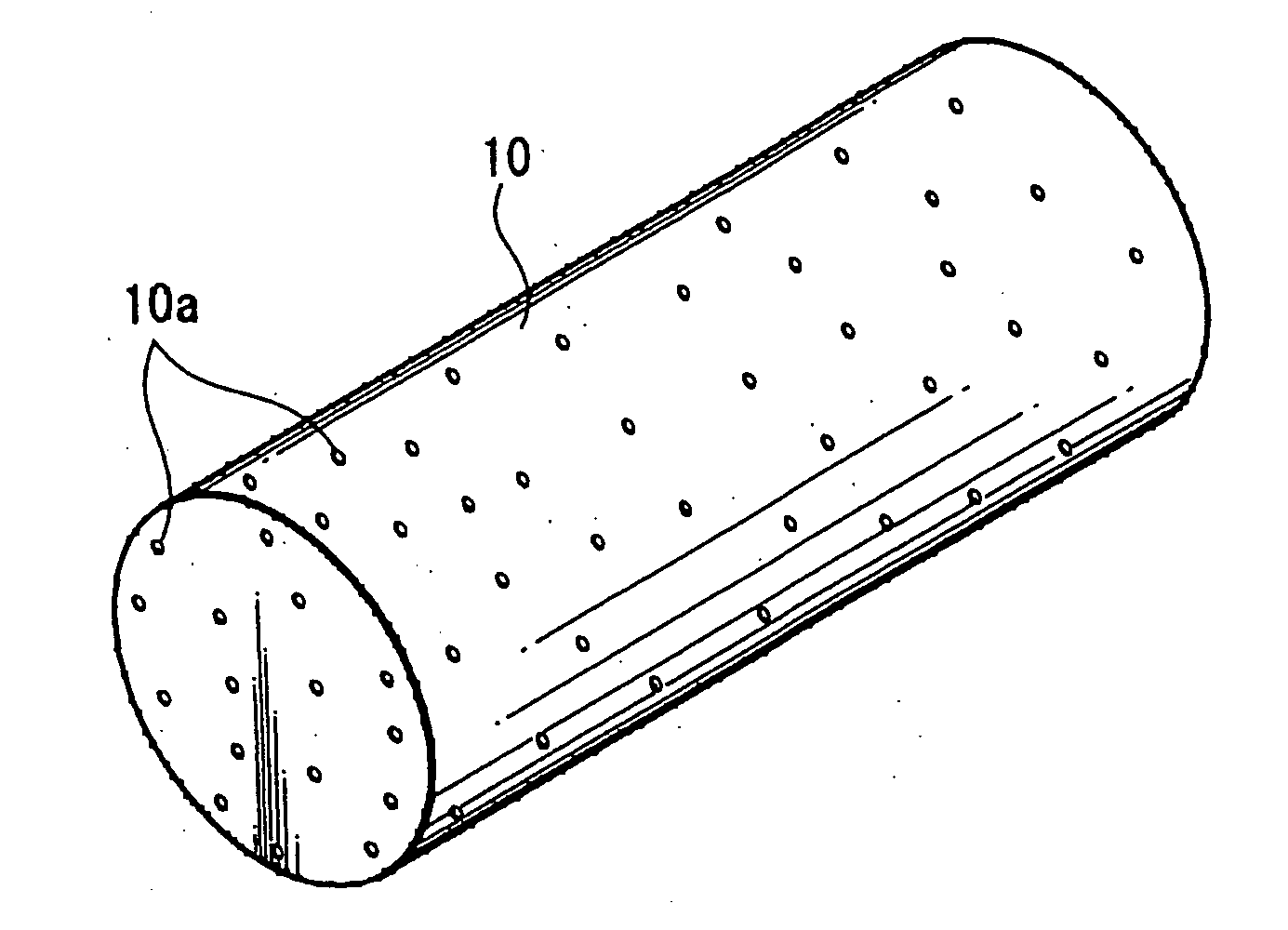
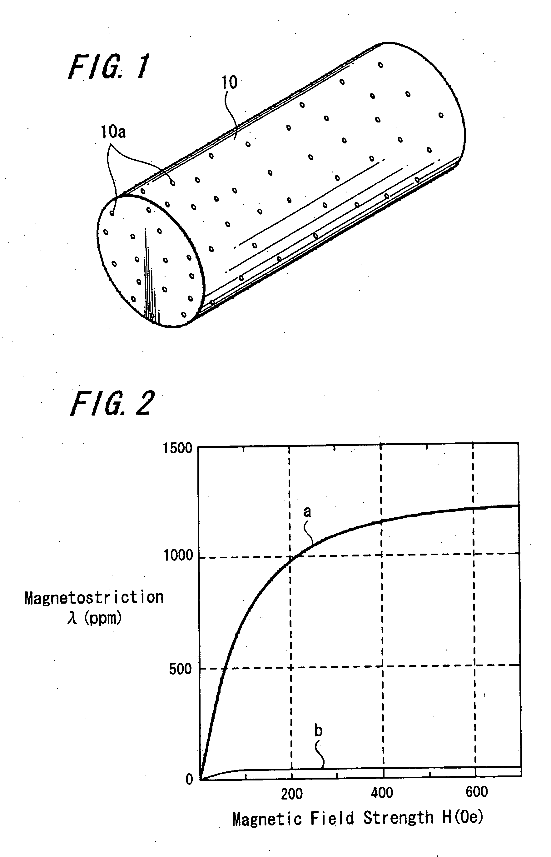
[0025] The impregnated composition material was impregnated into this magnetostrictive sintered material 10 and cured by using impregnation phenol resin (manufactured by Sumitomo Bakelite Company Limited under the trade name of “PR-9183B”) as the impregnated composition material as follows.
[0026] First, the magnetostrictive sintered material 10 is rinsed in a pre-treatment process. After that, this magnetostrictive sintered material 10 is set within a tank and this tank is evacuated to let air out of the holes 10a of the magnetostrictive sintered material 10. After that, the impregnation phenol resin that is the impregnated composition material is injected into this tank and the magnetostrictive sintered material 10 is dipped into this impregnation phenol resin.
[0027] After that, the impregnation phenol resin is impregnated into the holes 10a of the magnetostrictive sintered material 10 by returning the tank to the atmospheric pressure.
[0028] Next, the magnetos...
##ventive example 2
INVENTIVE EXAMPLE 2
[0030] Impregnation phenol resin (manufactured by Sumitomo Bakelite Company Limited under the trade name of “PR-9183B”) is used as an impregnated composition material, and powder (particle size thereof lies in a range of from 5 to 20 microns) of iron (that is, iron equivalent to S15C), which is a ferromagnetic material, is dispersed into this impregnation phenol resin with a weight ratio of “5” of impregnation phenol resin to “1” of iron powder. This mixed impregnation phenol resin product is impregnated and cured into the holes 10a of the magnetostrictive sintered material 10 as follows.
[0031] First, the magnetostrictive sintered material 10 is rinsed in the pre-treatment process. After that, the magnetostrictive sintered material 10 is set in a tank and the tank is evacuated to let air out of the holes 10a of the magnetostrictive sintered material 10. After that, the impregnation phenol resin in which the powder of the ferromagnetic material was dispersed is in...
PUM
| Property | Measurement | Unit |
|---|---|---|
| particle size | aaaaa | aaaaa |
| temperature | aaaaa | aaaaa |
| temperature | aaaaa | aaaaa |
Abstract
Description
Claims
Application Information
 - R&D
- Intellectual Property
- Life Sciences
- Materials
- Tech Scout
- Unparalleled Data Quality
- Higher Quality Content
- 60% Fewer Hallucinations
Browse by: Latest US Patents, China's latest patents, Technical Efficacy Thesaurus, Application Domain, Technology Topic, Popular Technical Reports.
© 2025 PatSnap. All rights reserved.Legal|Privacy policy|Modern Slavery Act Transparency Statement|Sitemap|About US| Contact US: help@patsnap.com


