Optical apparatus such as digital still camera, video camera, and interchangeable lens

a technology of optical apparatus and lens, applied in the field of optical apparatus, can solve the problems of weak strength of the wide position and hampered effort to reduce the size of the optical apparatus, and achieve the effect of uniformizing or enhancing the strength against an external for

Inactive Publication Date: 2008-01-22
CANON KK
View PDF4 Cites 0 Cited by
  • Summary
  • Abstract
  • Description
  • Claims
  • Application Information

AI Technical Summary

Benefits of technology

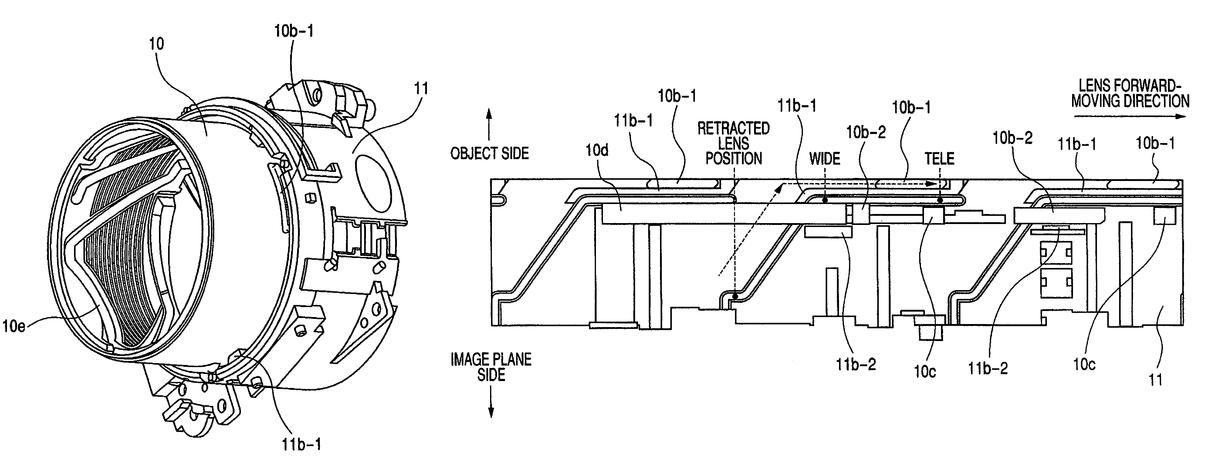
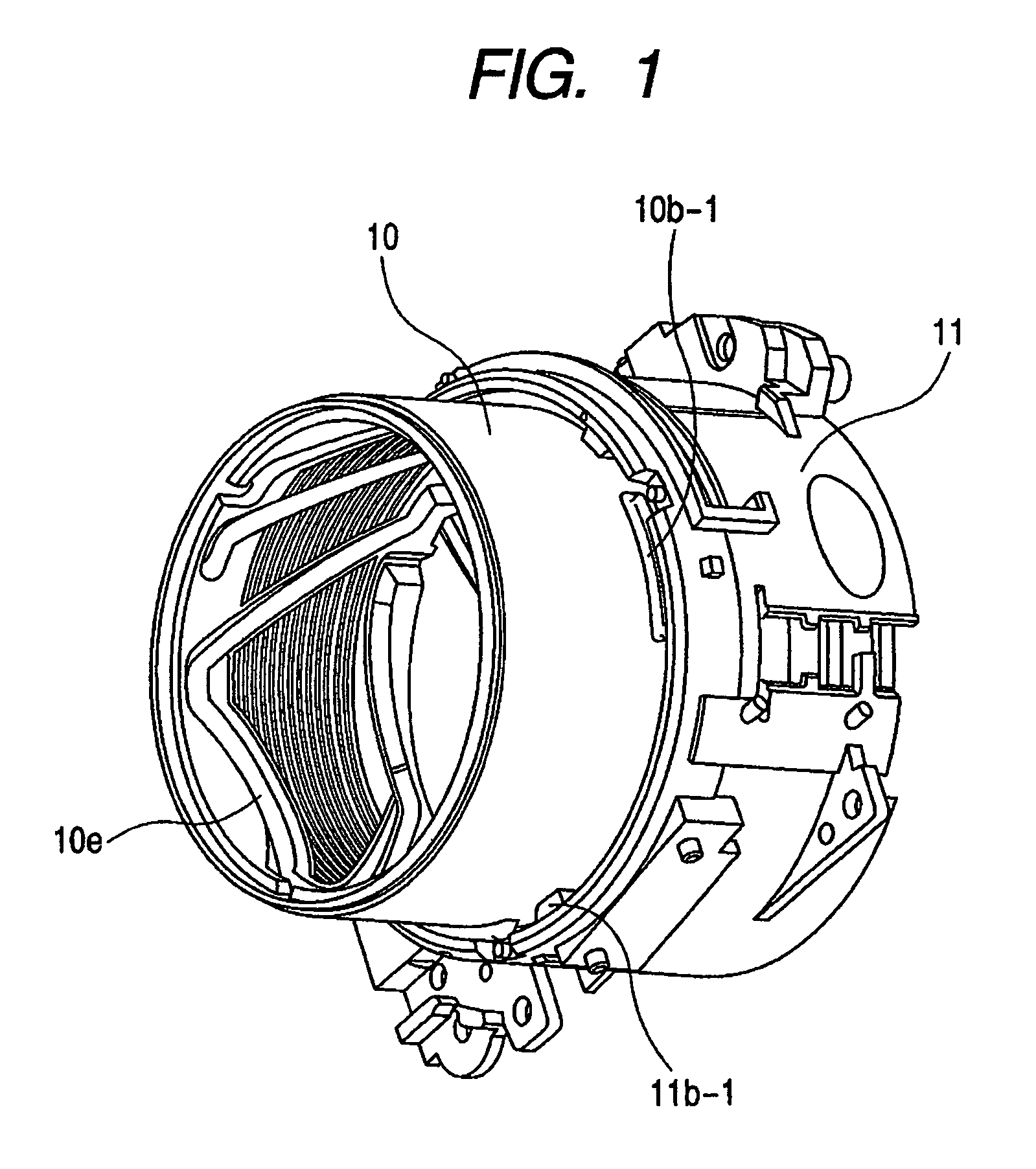
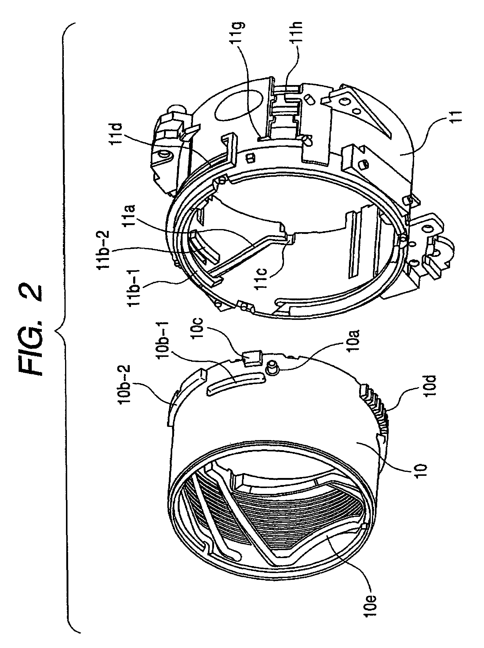
[0012]The present invention has been made in consideration of the above situation, and it is an object of the present invention to provide an optical apparatus whose strength against an external force can be uniformized or enhanced without increasing the size of a lens barrel.

Problems solved by technology

This causes a problem in that the vicinity of the wide position is weak in strength against an external force in comparison with the other portions in the zoom region.
As a result, any effort to reduce the size of the optical apparatus is hampered.

Method used


Image

  • Optical apparatus such as digital still camera, video camera, and interchangeable lens
  • Optical apparatus such as digital still camera, video camera, and interchangeable lens
  • Optical apparatus such as digital still camera, video camera, and interchangeable lens

Examples


Embodiment Construction

[0030]The present invention will now be described in detail below with reference to the drawings showing preferred embodiments thereof.

[0031]FIGS. 9 to 12 each show a construction of a digital still camera (a photographic apparatus or an optical apparatus) according to the embodiment of the present invention. FIG. 9 is an exploded perspective view showing a construction of a lens barrel unit of the digital still camera. FIG. 10 is a sectional view showing a construction of the digital still camera in a non-service state (a lens-retracted lens barrel condition). FIG. 11 is a sectional view showing the construction of the digital still camera in a service state (a lens-protruding lens barrel condition) at a wide angle (wide) position. FIG. 12 is a sectional view showing the construction of the digital still camera in the service state at a telescopic (tele) position.

[0032]Referring to FIGS. 9 to 12, a unit base member 1, which serves as a base of the lens barrel unit, is fixed to a ca...


PUM


Abstract

An optical apparatus having a first member and a second member rotating about an optical axis with respect to the first member. One of the members has a cam portion; the other has a cam follower portion engaged with the cam portion which drives the first and second members relatively in an optical axis direction. The first member has first and second portions protruding toward the second member side separated from each other in the optical axis direction; the second member has third and fourth portions protruding toward the first member side separated from each other in the optical axis direction and abuts on the first and second portions, respectively; and the fourth portions are provided in a circumferential direction of the second member and include protruding portions for transmitting power.

Description

BACKGROUND OF THE INVENTION[0001]1. Field of the Invention[0002]The present invention relates to an optical apparatus such as a digital still camera, a video camera, and an interchangeable lens, and more particularly, to a structure for preventing a cam engaging portion for driving a lens barrel of the optical apparatus from being disengaged when an external force is applied to the lens barrel.[0003]2. Related Background Art[0004]In one basic construction of a lens barrel that expands and contracts in an optical axis direction, a cam follower portion provided on a cam barrel for cam-driving a lens holding barrel for holding a lens is engaged with a cam groove portion provided in a fixed barrel, and the cam barrel rotates around the optical axis and is thereby driven in the optical axis direction, so the lens holding barrel is also driven in the optical axis direction.[0005]In the lens barrel described above, when an external force is applied to a front end of the lens barrel, for ex...

Claims


Application Information

Patent Timeline
Patent Type & Authority Patents(United States)
IPC IPC(8): G02B15/14
CPCG03B17/14H04N5/2254
Inventor MASUKI, AKIHIKO
Owner CANON KK
Why Eureka
Try Eureka