Pinch roll apparatus and method for operating the same

a technology of pinch roll and pinch roller, which is applied in the direction of roll mill control devices, metal rolling arrangements, manufacturing tools, etc., can solve the problems of cast strip, strip breakage, casting operation shutdown, etc., and achieve the effect of improving the processing capability of cast strip plant, accurate steering of strip, and improving accuracy

Active Publication Date: 2006-09-21
NUCOR CORP
View PDF3 Cites 2 Cited by
  • Summary
  • Abstract
  • Description
  • Claims
  • Application Information

AI Technical Summary

Benefits of technology

[0005] Accordingly, there has been a need for pinch rolls that better control the steering of the strip within closed tolerances to improve the processing capabilities of the cast strip plant, and at the same time, provide steering of the strip by the pinch rolls that can be automatically controlled with improved accuracy. The resulting pinch rolls apparatus of the present invention solves this problem in continuous casting of thin cast strip and in apparatus that is also useful in other applications. By reason of the geometry of the apparatus, there is no path for the strip through the pinch rolls where the strip can pass without maintaining contact of the strip across its width with surfaces of the pinch rolls, and at the same time steering the strip accurately and stabilizing the lateral movement of the strip relative to the pinch rolls.
[0090] g. steering the thin cast strip between the pinch rolls by controlling the tilt of the upper pinch roll relative to the lower pinch roll with the pinch tilt drive.

Problems solved by technology

If exposed to normal atmosphere, it would suffer very rapid scaling due to oxidation at such high temperatures.
A problem occurs however in steering the cast strip through the pinch rolls at casting speeds.
The strip tends to wander, which can cause difficulties in processing of the strip downstream of the caster and, in some circumstances, breakage of the strip and shutdown of the casting operation.
Also, there can be localized deformation and tearing of the strip.
This steering problem is caused by a lack of contact of the pinch rolls with the strip across its width as illustrated in FIG. 1.

Method used


Image

  • Pinch roll apparatus and method for operating the same
  • Pinch roll apparatus and method for operating the same
  • Pinch roll apparatus and method for operating the same

Examples


Embodiment Construction

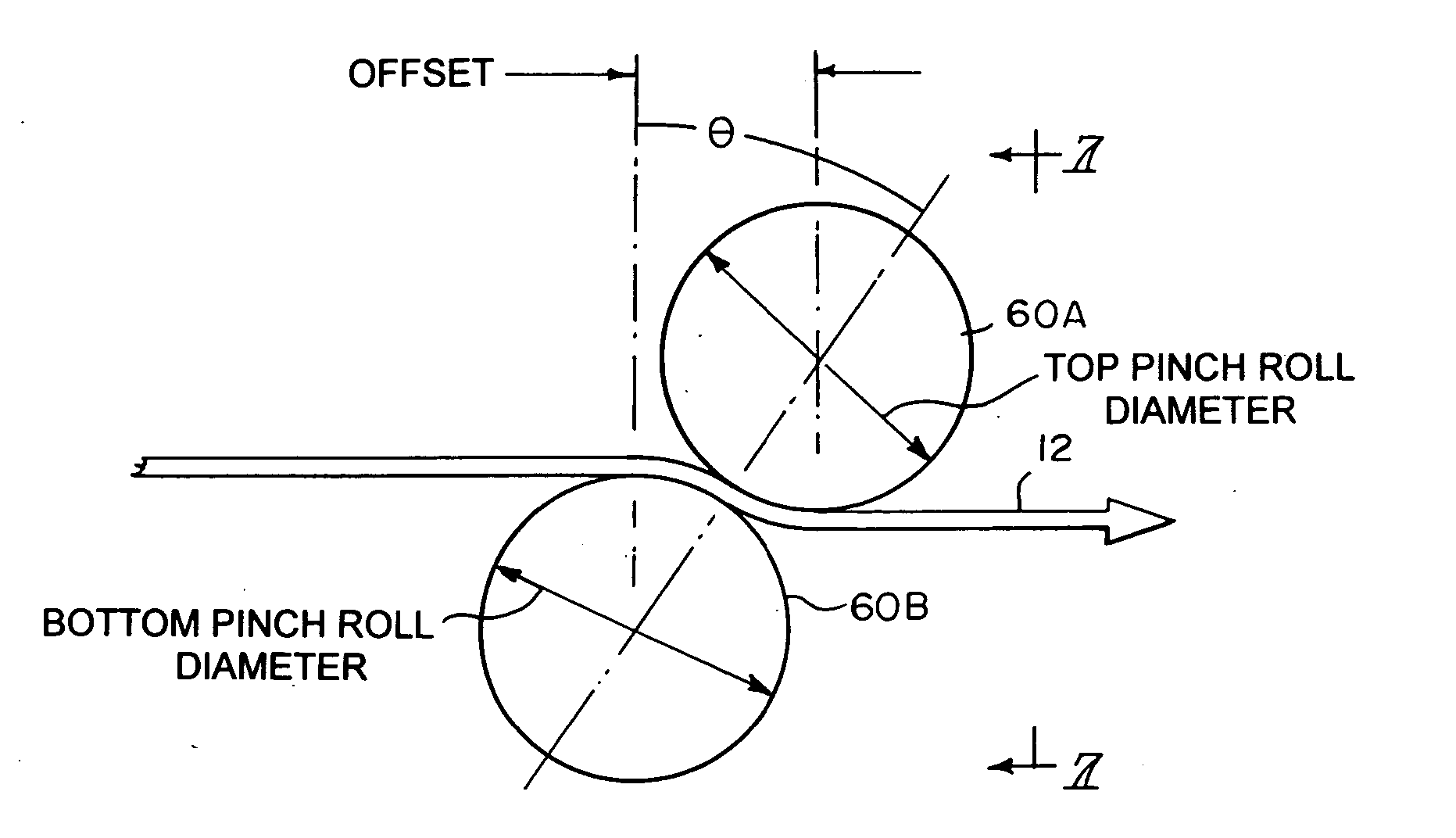
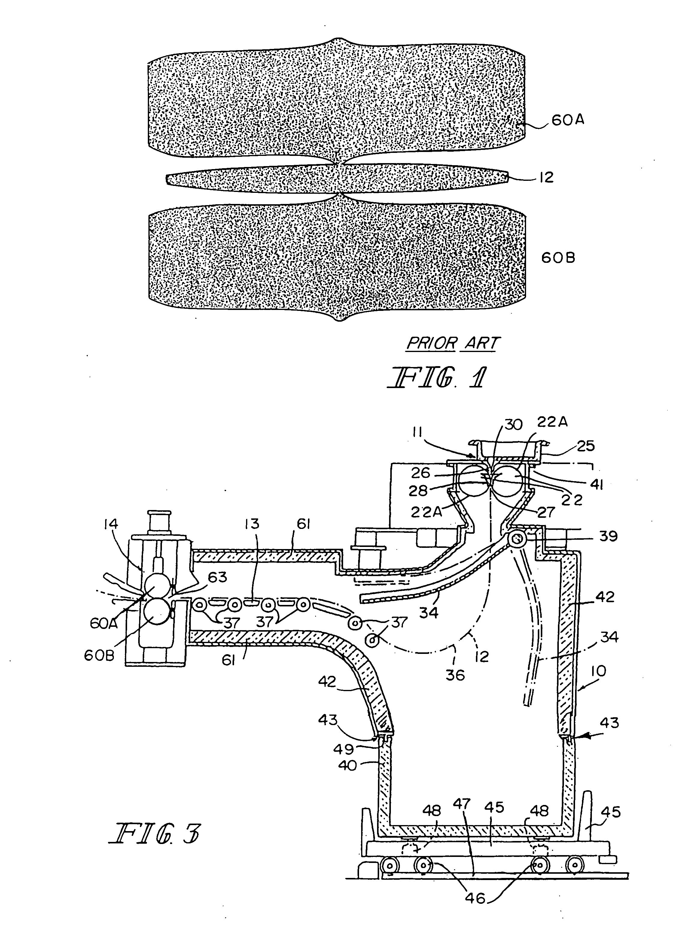
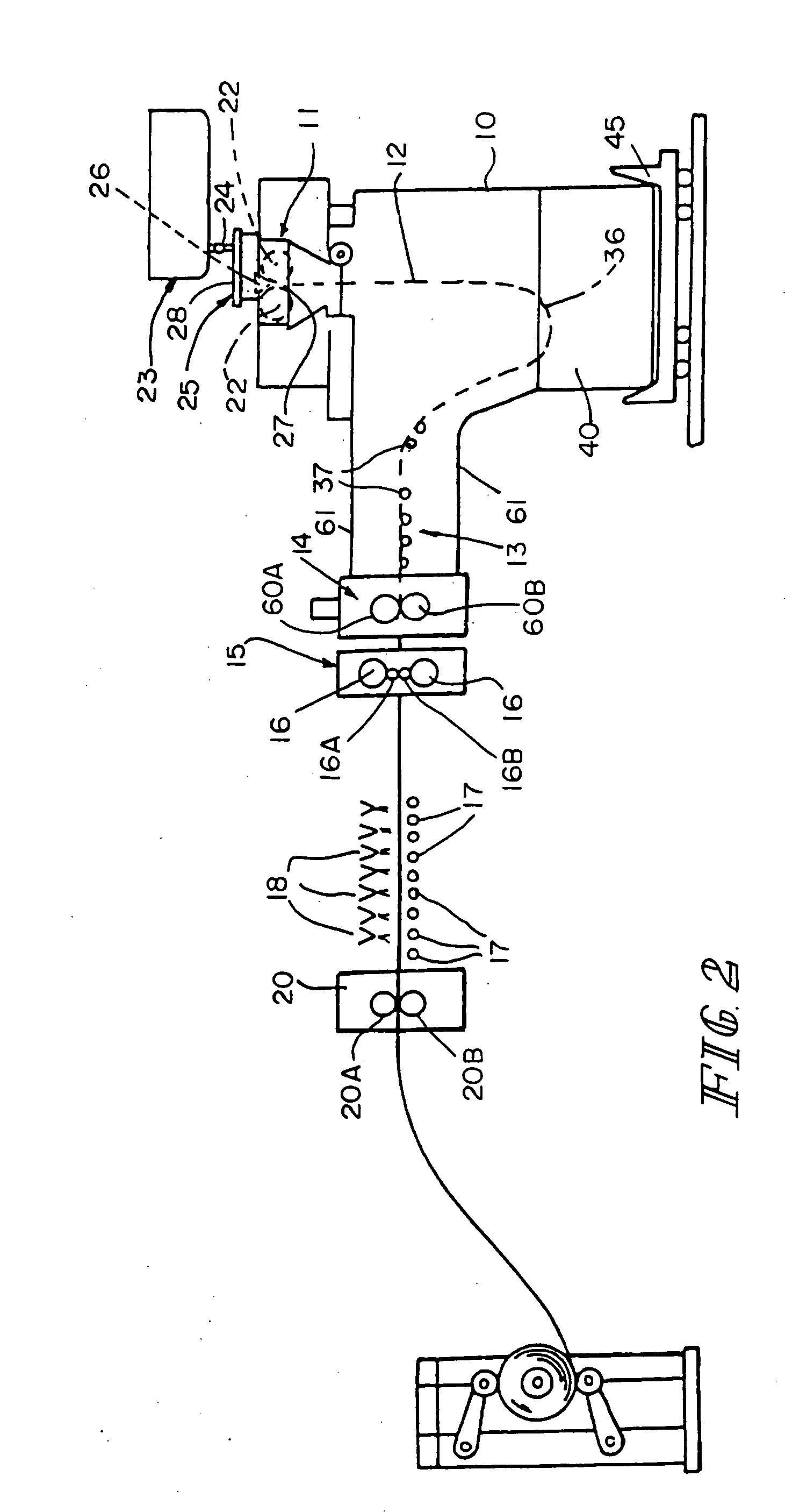
[0125] The illustrated casting and rolling installation comprises a twin-roll caster denoted generally by 11 which produces thin cast steel strip 12. Thin cast steel strip 12 passes downwardly and then into a transient path across a guide table 13 to a pinch roll stand 14. After exiting the pinch roll stand 14, thin cast strip 12 may optionally pass into and through hot rolling mill 15 comprised of back up rolls 16 and upper and lower work rolls 16A and 16B, where the thickness of the strip may be reduced. The strip 12, upon exiting the rolling mill 16, passes onto a run out table 17, where it may be forced cooled by water jets 18, and then through pinch roll stand 20, comprising a pair of pinch rolls 20A and 20B, and then to a coiler 19, where the strip 12 is coiled, for example, into 20 ton coils.

[0126] Twin-roll caster 11 comprises a pair of laterally positioned casting rolls 22 having casting surfaces 22A, and forming a nip 27 between them. Molten metal is supplied during a cas...


PUM

PropertyMeasurementUnit
diameteraaaaaaaaaa
diameteraaaaaaaaaa
diameteraaaaaaaaaa

Abstract

Pinch roll apparatus has a pair of pinch rolls each having a diameter between 300-1500 millimeters positioned to form a nip through which metal strip can be continuously fed. The pinch rolls are positioned one above the other with the axes of the pinch rolls offset in the direction of travel of strip, with the upper pinch roll offset positioned between 10 and 130 mm downstream of the direction of travel of the strip through the pinch rolls. A rotational drive counter rotates the pinch rolls to cause strip to pass through the nip of the pinch rolls. A tilt drive tilts the upper pinch rolls by a tilt between 0.5 and 5.0 mm to control steering of the strip passing through the pinch rolls. The steering of the tilt drive may be automatically controlled through a controller actuated by a sensor.

Description

BACKGROUND AND SUMMARY OF THE INVENTION [0001] This invention relates to pinch rolls and particularly to those used in continuous casting of thin steel strip in a twin-roll caster. [0002] In a twin roll caster, molten metal is introduced between a pair of counter-rotated horizontal casting rolls which are cooled so that metal shells solidify on the moving roll surfaces, and are brought together at the nip between them to produce a solidified strip product delivered downwardly from the nip between the casting rolls. The term “nip” is used herein to refer to the general region at which the casting rolls are closest together. The molten metal may be poured from a ladle through a metal delivery system comprised of a tundish and a core nozzle located above the nip to form a casting pool of molten metal supported on the casting surfaces of the rolls above the nip and extending along the length of the nip. This casting pool is usually confined between refractory side plates or dams held in...

Claims


Application Information

Patent Timeline
Patent Type & Authority Applications(United States)
IPC IPC(8): B22D11/128B22D11/00
CPCB22D11/128B22D11/20B21B37/68B21B39/14B22D11/12
Inventor ONDROVIC, JAY JONBRITANIK, RICHARDDOMANTI, TINOWALLACE, GLEN
Owner NUCOR CORP
Why Eureka
Try Eureka