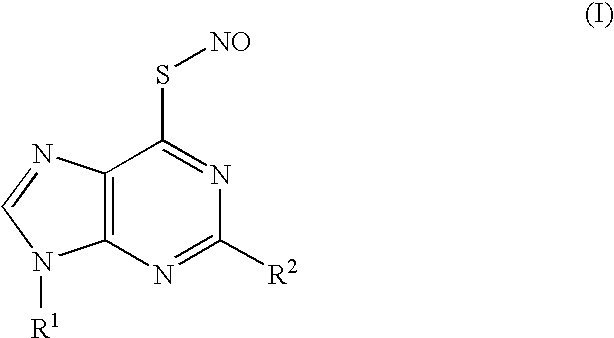
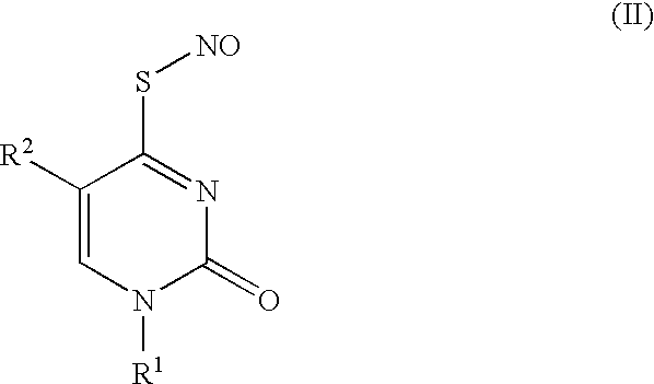
Thionucleoside s-nitrosyl derivative
a technology of thionucleosides and nitrosyls, applied in the field of manipulating nucleic acids, can solve the problem of low repair efficiency
- Summary
- Abstract
- Description
- Claims
- Application Information
AI Technical Summary
Problems solved by technology
Method used
Image


Examples
example 1
Synthesis of thionucleoside-S-nitrosyl derivative
[0070] 2′-Deoxy-6-thioguanosine (as a t-butyldimethylsilyl derivative) synthesized in a known manner (M. Kadokura, T. Wada, K. Seio, and M. Sekine J. Org. Chem., 65, 5104-5113 (2000)) (0.25 μmol), SNAP (2, S-nitroso-N-acetylpenicillamine) (0.25 μmol) and triethylamine (0.28 μmol) were dissolved in methanol (500 μl) and stirred at 0° C. The reaction solution was directly injected into HPLC-MS to measure ESI-MS (FIG. 4). HPLC conditions are as follows.
[0071] Column: Symmetry C18 2×50 mm
[0072] Column temperature: 25° C.
[0073] Mobile phase: A=H2O, B=MeOH, % B=60-100% / 5 min then 100% 20 min
[0074] Flow rate: 0.2 mL / min
[0075] UV: 254 nm
[0076] The HPLC eluate was separated by a splitter, about 1 / 40 (about 5 μL) of which was then introduced into a mass spectrometer. Mass spectrometry was performed in positive mode ESI-TOF. MS conditions (Applied biosystem Mariner System 5299) were set as follows: Spray Tip Potential, 4006, Nozzle potent...
example 2
Synthesis of Oligonucleic Acid
[0080] A 5′-O-dimethoxytrityl-3′-O-(2-cyanoethyl-N,N-diisopropylphosphoroamidite) form of S-(2-cyanoethyl)-2′-deoxy-6-thioguanosine, which had been synthesized in a known manner, was introduced into an oligonucleotide using a DNA synthesizer (model name: DNA / RNA Synthesizer, Applied Biosystems), followed by heating in 28% aqueous ammonia at 55° C. for 5 hours to obtain Oligonucleotide 6 (FIG. 5, Scheme 6; SEQ ID NO: 1). Oligonucleotide 6 (150 nmol) and SNAP (3 μmol) were dissolved in 300 μl carbonate buffer (pH 10.0) and allowed to stand at room temperature for 12 hours. After confirming the progress of the reaction by HPLC, a newly generated peak was isolated under the same HPLC conditions to thereby obtain Oligonucleotide 7 (SEQ ID NO: 2) shown in FIG. 5, Scheme 7. The yield was 31%, as measured by V absorbance at 260 nm. Moreover, when the molecular weight was determined by MALDI-TOF MASS, the measured value for molecular weight was found to be 4796...
example 3
[NO+] Generation Test by Digestion of Nucleotide 7
[0081] Into a fluorescence cell, a solution of Oligonucleotide 7 (FIG. 5) in MES buffer (0.05 M MES, 0.1 M NaCl, adjusted to pH 5 or pH 7, 1.5 mL, Oligonucleotide 7: 0.5 μM) was introduced and supplemented with DAF-2 (diaminofluoroscein, final concentration: 4 μM), followed by stirring at 25° C. The fluorescence spectrum of this reaction solution was measured over time (excitation wavelength: 488 nm, fluorescence wavelength: 500-600 nm). Simultaneously, 1 μl aliquots were also sampled over time from this solution and injected into HPLC to monitor the conversion of Oligonucleotide 7 into Oligonucleotide 6.
[0082] Column: Nacalai tesque, COSMOSIL 5C18-MS (4.6×250 mm)
[0083] Mobile phase: [0084] A: 0.1M TEAA Buffer, B: CH3CN [0085] B: 10% to 30% / 20 min, 40% / 30 min, linear gradient
[0086] Flow rate: 1.0 ml / min
[0087] UV-monitor: 260 nm
[0088] The relative fluorescence intensity at 512 nm and percentage conversion into Oligonucleotide 6 ...
PUM
| Property | Measurement | Unit |
|---|---|---|
| Length | aaaaa | aaaaa |
Abstract
Description
Claims
Application Information
 - R&D
- Intellectual Property
- Life Sciences
- Materials
- Tech Scout
- Unparalleled Data Quality
- Higher Quality Content
- 60% Fewer Hallucinations
Browse by: Latest US Patents, China's latest patents, Technical Efficacy Thesaurus, Application Domain, Technology Topic, Popular Technical Reports.
© 2025 PatSnap. All rights reserved.Legal|Privacy policy|Modern Slavery Act Transparency Statement|Sitemap|About US| Contact US: help@patsnap.com