
Rotary ram compressor

a compressor and ram technology, applied in the direction of machines/engines, stators, liquid fuel engines, etc., can solve the problems of increasing the temperature of pressurized gases supplied, reducing increasing so as to improve the operating efficiency of any subsequent compressor stage, reduce the overall rise in the temperature of pressurized gases, and improve the channel configuration

Inactive Publication Date: 2006-09-07
RRC SGTE TECH
View PDF8 Cites 10 Cited by
  • Summary
  • Abstract
  • Description
  • Claims
  • Application Information

AI Technical Summary

Benefits of technology

[0006] Accordingly, the present invention provides a rotary ram compressor having improved channel configuration, which decreases the overall rise in the temperature of the pressurized gases provided by the compressor, and thus improving the operating efficiency of any subsequent compressor stage.
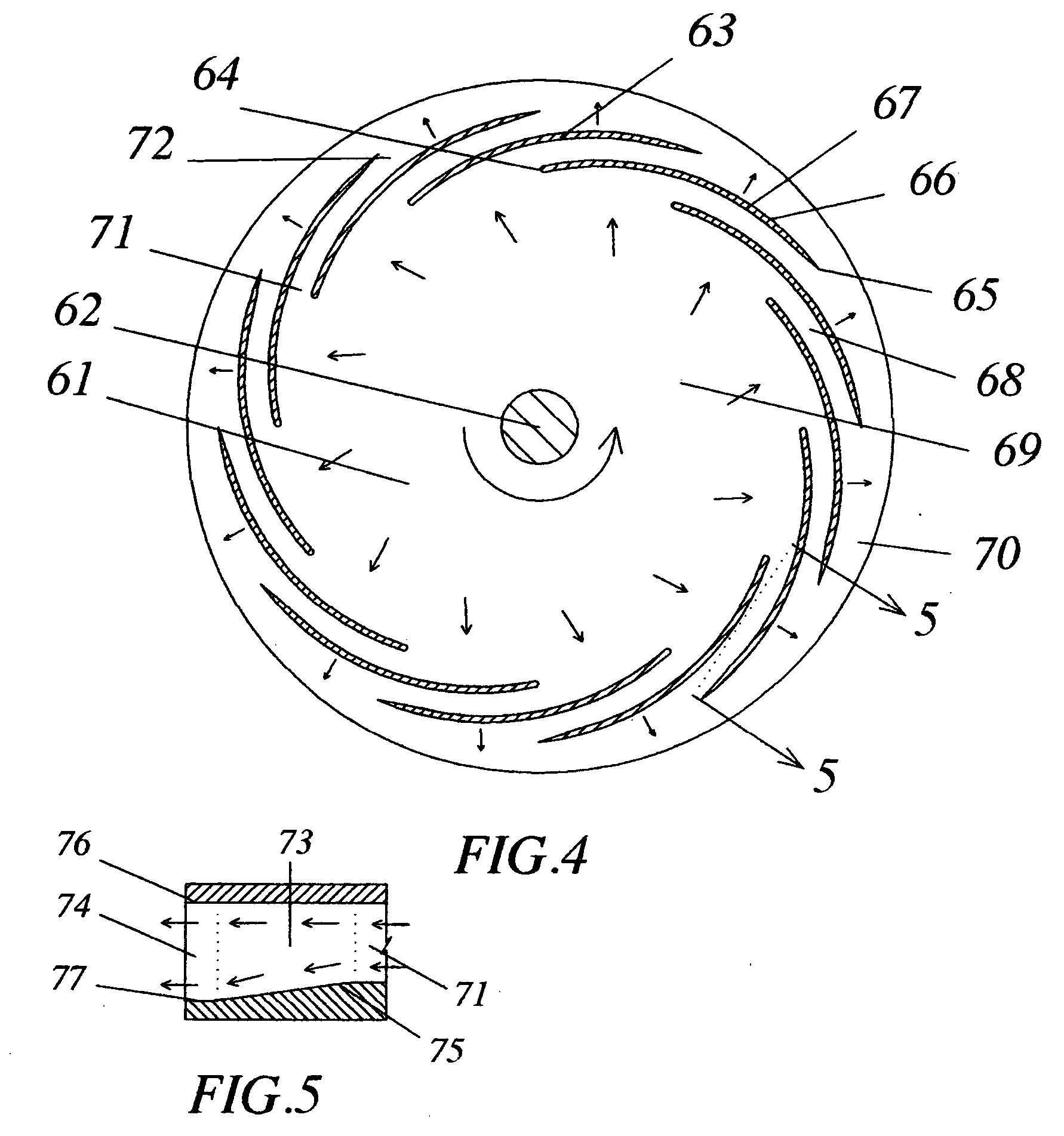
[0027] Also, as minimal acceleration of the gases occurs within the channels, in the form of gradual displacement in either a relatively radially inward or a relatively radially outward direction, according to the type of the rotary ram compressor used, the resulting rise in the temperature of the pressurized gases will be minimal, with marked improvement in the efficiency of subsequent compression, when needed, and which also enables recovering more heat energy from the exhaust gases, when used in gas turbine engines provided with heat exchangers, which will decrease the overall heat energy emission from the power plant and improve its overall operating efficiency.
[0028] Any of the previous rotary ram compressor embodiments discussed herein before, can be used as a vacuum pump, to decrease the pressure of a gas inside a container, by freely communicating the exit passage of the rotary ram compressor to the surrounding atmosphere, and communicating its inlet passage(s) with the container. In operation, the gas inside the container is rammed out of it, through the channels confined between the vanes of the rotor assembly of the rotary ram compressor, and is discharged to the surrounding atmosphere, and thus, decreases the pressure of the gas inside the container.

Problems solved by technology

The admission of a diverging stream of gases will be associated with turbulence of the gases at the point of admission, which leads to an additional increase in the temperature of pressurized gases supplied by the compressor, and thus decreasing the operating efficiency of any following compressor stage.

Method used


Image

  • Rotary ram compressor
  • Rotary ram compressor
  • Rotary ram compressor

Examples


Embodiment Construction

[0037] The present invention provides a rotary ram compressor having improved channel configuration, which decreases the overall rise in the temperature of the pressurized gases provided by the compressor, and thus improving the operating efficiency of any subsequent compressor stage.

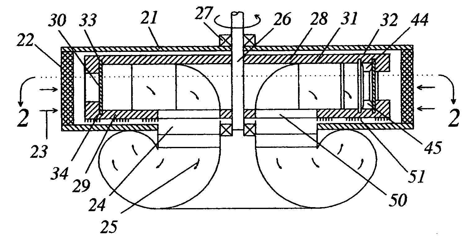
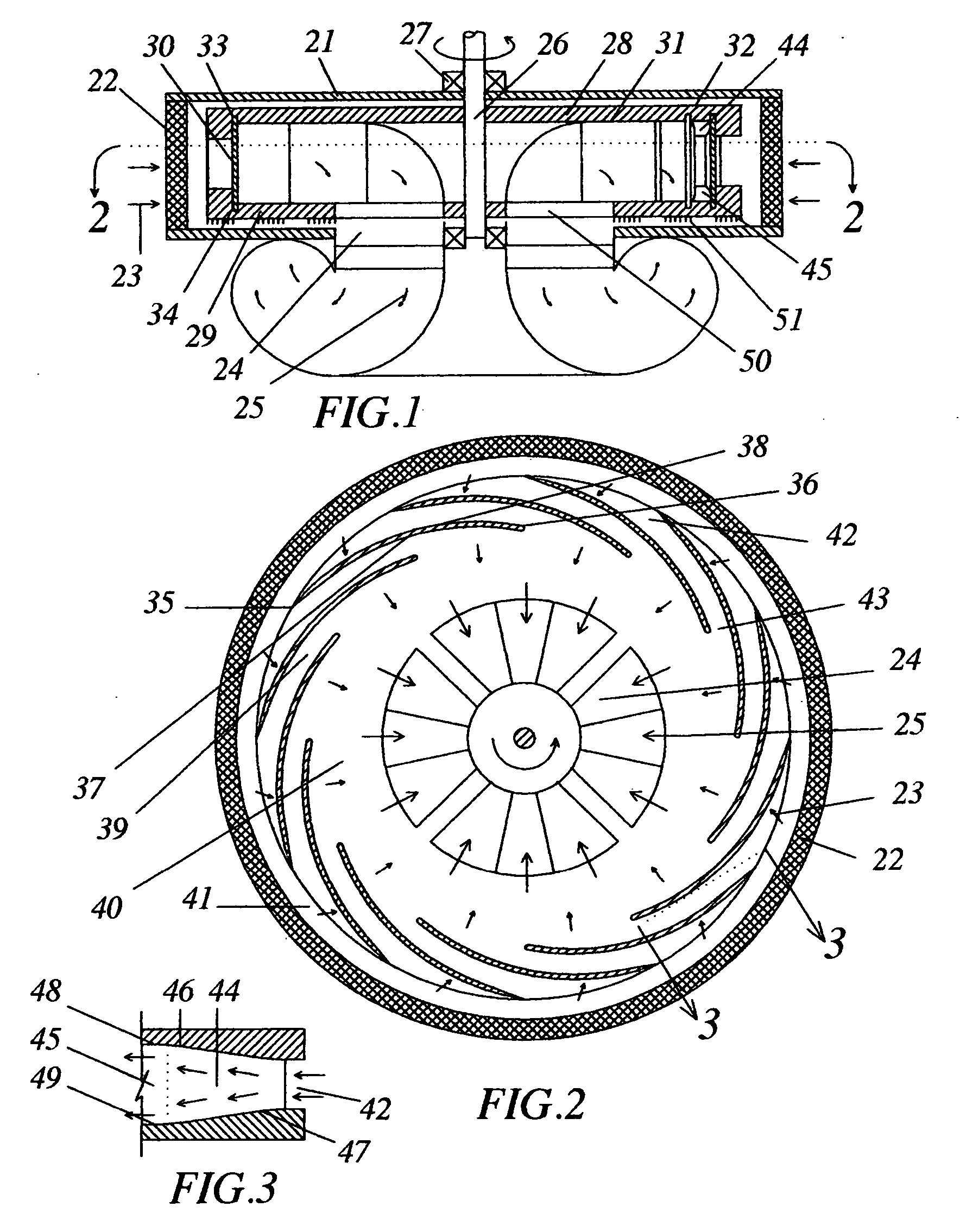
[0038] In a preferred embodiment, the rotary ram compressor comprises a stationary casing having an inlet passage for admission of gases and an exit passage for discharge of the pressurized gases; a drive shaft supported by an arrangement of bearings, for rotation in a given direction inside the casing and extending to a drive receiving end located outside the casing; and a rotor assembly housed inside the casing. The rotor assembly includes a first disk surrounding the drive shaft and lying in a first plane transverse to the rotational axis of the drive shaft, a second disk surrounding the drive shaft and lying in a second plane transverse to the rotational axis of the drive shaft and axially spaced f...


PUM


Abstract

A rotary ram compressor for use in gas turbine engines and the like, having a plurality of vanes attached to discs, with the opposing parts of each two adjacent vanes and the opposing parts of the disks' surfaces confined between the opposing parts of the surfaces of the two adjacent vanes defining a channel in-between. Each channel is formed of two successive freely communicating portions: a first diverging inlet portion; and a second constant cross-sectional area outlet portion. In operation, gases are rammed into the first diverging inlet portion of the channel and are gradually displaced to the second constant cross-sectional area outlet portion of the channel, while being diverged, resulting into a rise in the static pressure energy of the gases, followed by smoothening of the stream of flow of the pressurized gases within the second constant cross-sectional area outlet portion of the channel.

Description

FIELD OF THE INVENTION [0001] The present invention relates to a rotary ram compressor and, more particularly, to a rotary ram compressor convenient for use in gas turbine engines and the like, and having improved channel configuration, which decreases the overall rise in the temperature of the pressurized gases provided by the compressor, and thus improving the operating efficiency of any subsequent compressor stage. BACKGROUND OF THE INVENTION [0002] Rotary ram compressors are disclosed in the inventor's earlier International Patent Application serial number: PCT / US00 / 17044, entitled “Rotary ram fluid pressurizing machine”, wherein the phenomenon of ram pressure rise, which occurs when a gas is rammed into a suitably shaped diffuser moving at a high speed, is utilized to develop a pressure gradient between two points across a gas stream. In an exemplary embodiment, vanes attached to rotary disks form channels, which act as diffusers when the disks are rotated, wherein the kinetic ...

Claims


Application Information

Patent Timeline
IPC IPC(8): F04D29/44
CPCF04D17/02F04D29/282
Inventor AWDALLA, ESSAM T.
Owner RRC SGTE TECH
Learn More