Inverter units

a technology of inverter units and power supply components, applied in the direction of dc-ac conversion without reversal, process and machine control, instruments, etc., can solve the problems of rapid dc power source voltage drop, stop rotation of the motor, excess current flow, etc., and achieve the effect of stably and accurately

Inactive Publication Date: 2006-09-07
SANDEN CORP
View PDF7 Cites 6 Cited by
  • Summary
  • Abstract
  • Description
  • Claims
  • Application Information

AI Technical Summary

Benefits of technology

[0010] Accordingly, it is an object of the present invention to provide an inverter unit which may obtain consistently a desirable output voltage stably and accurately even if a voltage of a power source fluctuates, when a voltage of a DC power source is converted into a pulse train-like, pseudo-AC voltage using an inverter circuit with a plurality of switching elements.
[0016] In such an inverter unit according to the present invention, actually output voltage (e.g., high output voltage or low output voltage) is detected, an output duty cycle is calculated based on the above-described equation, so that the output voltage becomes, for example, a set value of the output indicator (i.e., a target output voltage), and PWM control is accomplished. Therefore, irrespective of a voltage reduction of a power source or a fluctuation of a voltage of a power source, a desirable output voltage may be obtained stably. For example, when voltage is output to a motor, an output effective voltage to the motor may be controlled at a target value stably and accurately.
[0018] Thus, in the inverter unit according to the present invention, because the output duty is determined by detecting an actual output voltage, even if the voltage of the DC power source fluctuates, regardless of the amount and composition of the fluctuation and without occurrence of time delay relative to the fluctuation of the voltage of the power source, the output voltage may be controlled at a target voltage value stably and accurately. Therefore, when the present invention is applied to control an output to a motor, even if the voltage of the DC power source fluctuates, the rotational speed of the motor may be maintained at a target rotational speed stably and accurately. Further, the present invention may be achieved by a less complicated circuit.

Problems solved by technology

Nevertheless, a DC power source mounted on a vehicle, such as a battery, may generate a voltage fluctuation in relation to an electric load.
Further, even in a vehicle driven by an internal combustion engine, if the power of the DC power source is used in a large amount, the voltage of the DC power source may decrease rapidly.
Further, when decelerated, an excess current may flow, and in a worst case, the rotation of the motor is stopped by the operation of a protective circuit.
Nevertheless, when controlled by such a method, it may become difficult to obtain a desirable output stably and accurately.
In particular, in the above-described, control method, a time delay due to a processing speed of the control unit, or the like, may occur between the recognition of the fluctuation of the voltage of the DC power source and the adjustment of the duty cycle, and, therefore, it may be difficult to adjust the duty cycle quickly and properly.
Consequently, a fluctuation of rotational speed, excess current or lack of torque in the brushless motor, or the like, may occur.

Method used


Image

  • Inverter units
  • Inverter units
  • Inverter units

Examples


Embodiment Construction

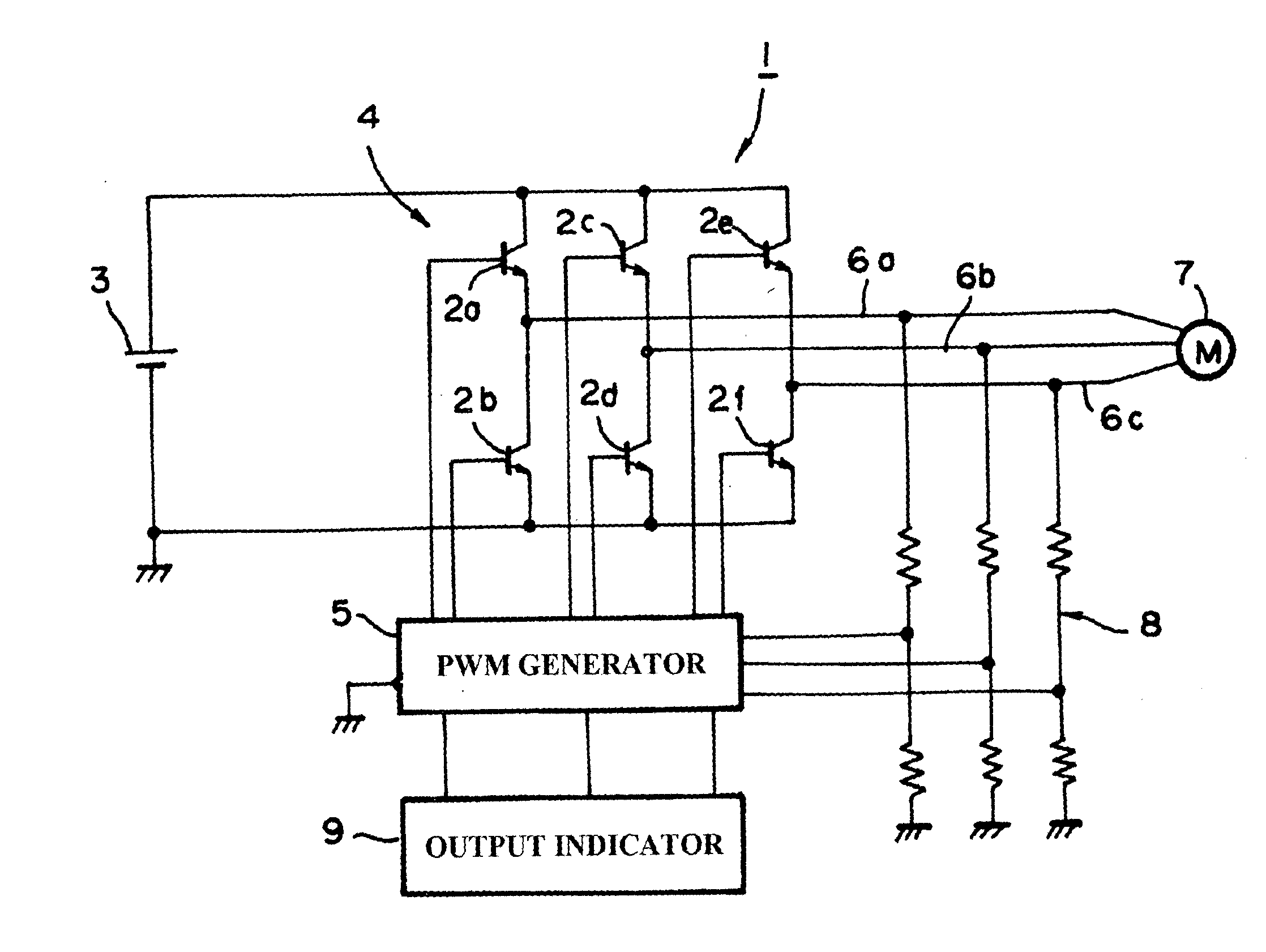
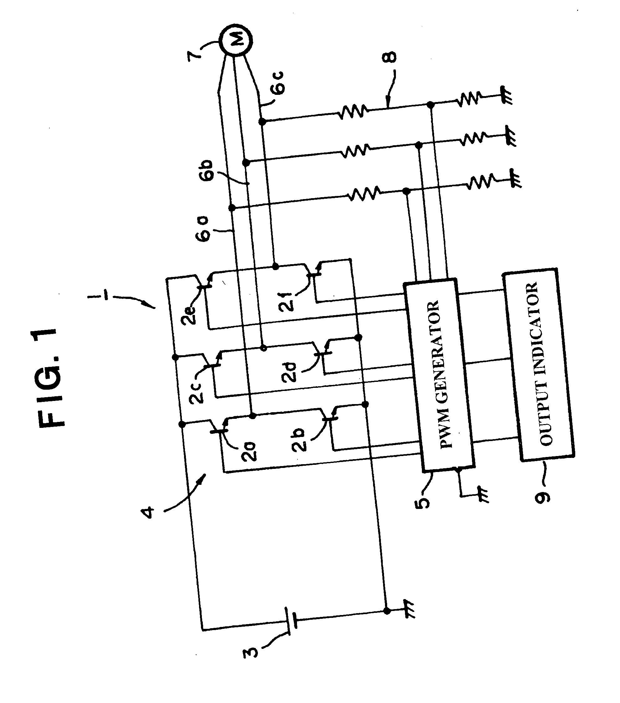
[0023]FIG. 1 depicts an inverter unit according to an embodiment of the present invention, and in particular, shows an embodiment in which it is formed as a motor drive, power source circuit, which outputs a pulse train-like, pseudo-AC voltage to a three-phase motor (e.g., a three-phase, brushless motor incorporated into a compressor and used in an air conditioning system for vehicles). In FIG. 1, inverter unit 1 comprises a DC power source 3 and an inverter circuit 4. Inverter circuit 4 comprises a plurality of pairs of switching elements, and each pair of switching elements 2a and 2b, 2c and 2d, and / or 2e and 2f are coupled in series to form each pair of switching elements. The plurality of pairs of switching elements are connected in parallel to DC power source 3 to form inverter circuit 4, so that a DC voltage of DC power source 3 is converted into a pulse train-like, pseudo-AC voltage and the converted, pseudo AC voltage is output. In the embodiment depicted in FIG. 1, inverter...


PUM


Abstract

An inverter unit includes a DC power source, an inverter circuit having two or more pairs of switching elements which are connected in parallel to the DC power source, so that a DC voltage of the DC power source is converted into a pulse train-like, pseudo-AC voltage output from the inverter circuit, and a PWM generator connected to the inverter circuit for adjusting the pseudo-AC voltage by pulse width modulation. Further, the inverter unit includes a voltmeter for detecting an actual, output voltage which is output from the inverter circuit, and a duty cycle controller for controlling an output duty cycle, so that the detected, actual, output voltage becomes a target output voltage. In this inverter unit, a desirable, output voltage may be obtained stably and accurately even if a voltage of a power source fluctuates.

Description

BACKGROUND OF THE INVENTION [0001] 1. Field of the Invention [0002] The present invention relates to inverter units, and more specifically, to inverter units which may stabilize an output from an inverter circuit, so that an output voltage does not vary even if a voltage of a power source varies, when a direct current (DC) voltage of a DC power source for use in vehicles is converted into a pulse train-like, pseudo-alternating current (AC) voltage using a plurality of switching elements. [0003] 2. Description of Related Art [0004] For example, a DC power source, such as a battery, may be mounted on a vehicle, and a DC voltage of the DC power source is used for various purposes and controls. This DC voltage of the DC power source is converted into a pulse train-like, pseudo-AC voltage by using an inverter circuit having a plurality of switching elements. The pseudo-AC voltage is used by a motor for driving a compressor (e.g., a brushless motor of a motor-driven compressor and the lik...

Claims


Application Information

Patent Timeline
IPC IPC(8): H02J1/00H02P6/06H02M7/48H02P6/08
CPCB60H1/00428H02M7/53875H02P27/08Y02T10/88
Inventor HIRONO, DAISUKESHIBUYA, MAKOTO
Owner SANDEN CORP
Why Eureka
Try Eureka