
Magnetic recording medium glass substrate and method of producing the same

a technology of magnetic recording medium and glass substrate, which is applied in the direction of magnetic materials for record carriers, instruments, transportation and packaging, etc., can solve the problems of insufficient low levitation characteristic and inability to realize the levitation stability of the magnetic head reading information from the glass substrate, and achieve the effect of improving levitation stability and less levitation amount of the magnetic head

Inactive Publication Date: 2006-08-31
HOYA CORP
View PDF7 Cites 35 Cited by
  • Summary
  • Abstract
  • Description
  • Claims
  • Application Information

AI Technical Summary

Benefits of technology

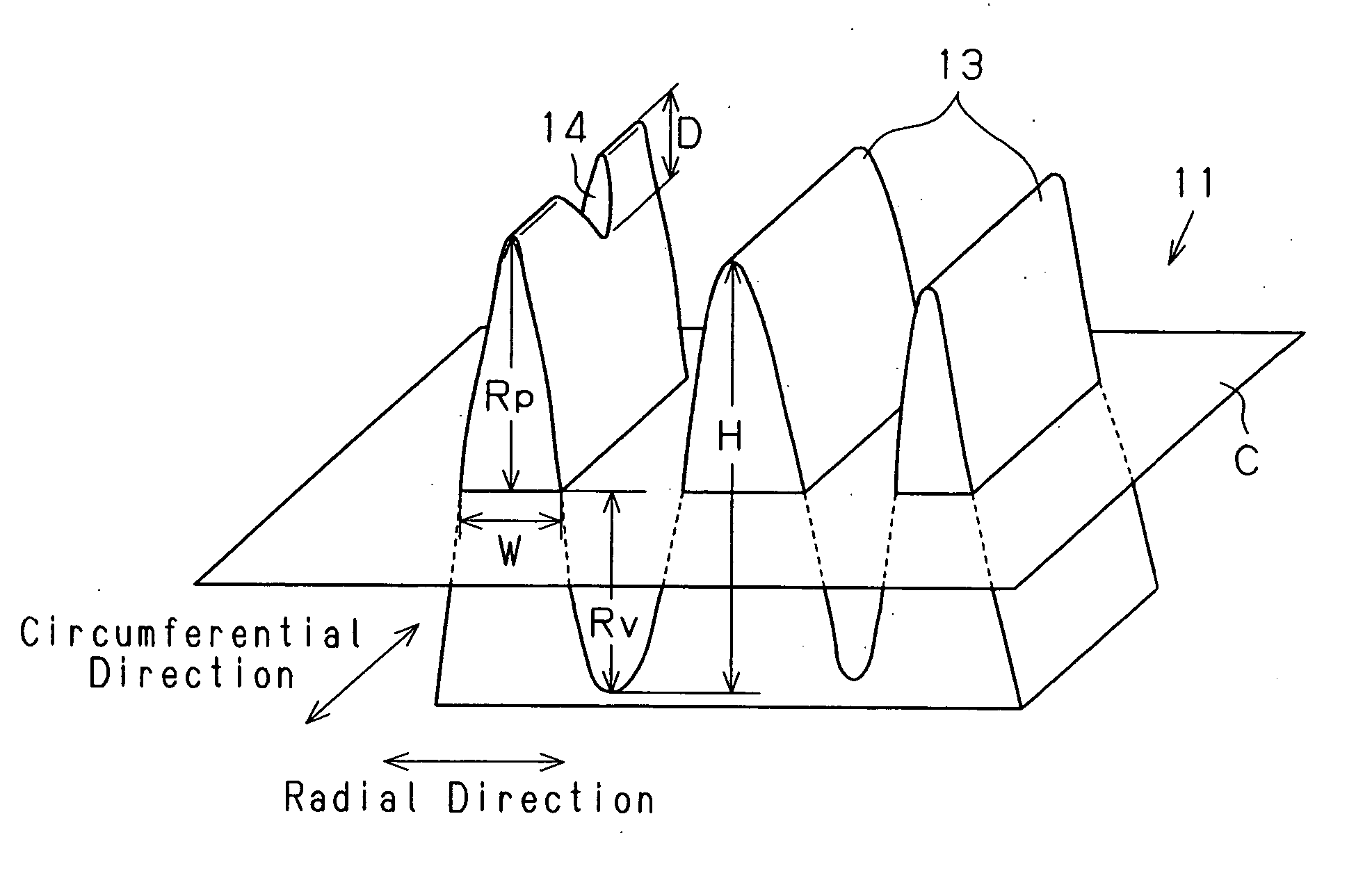
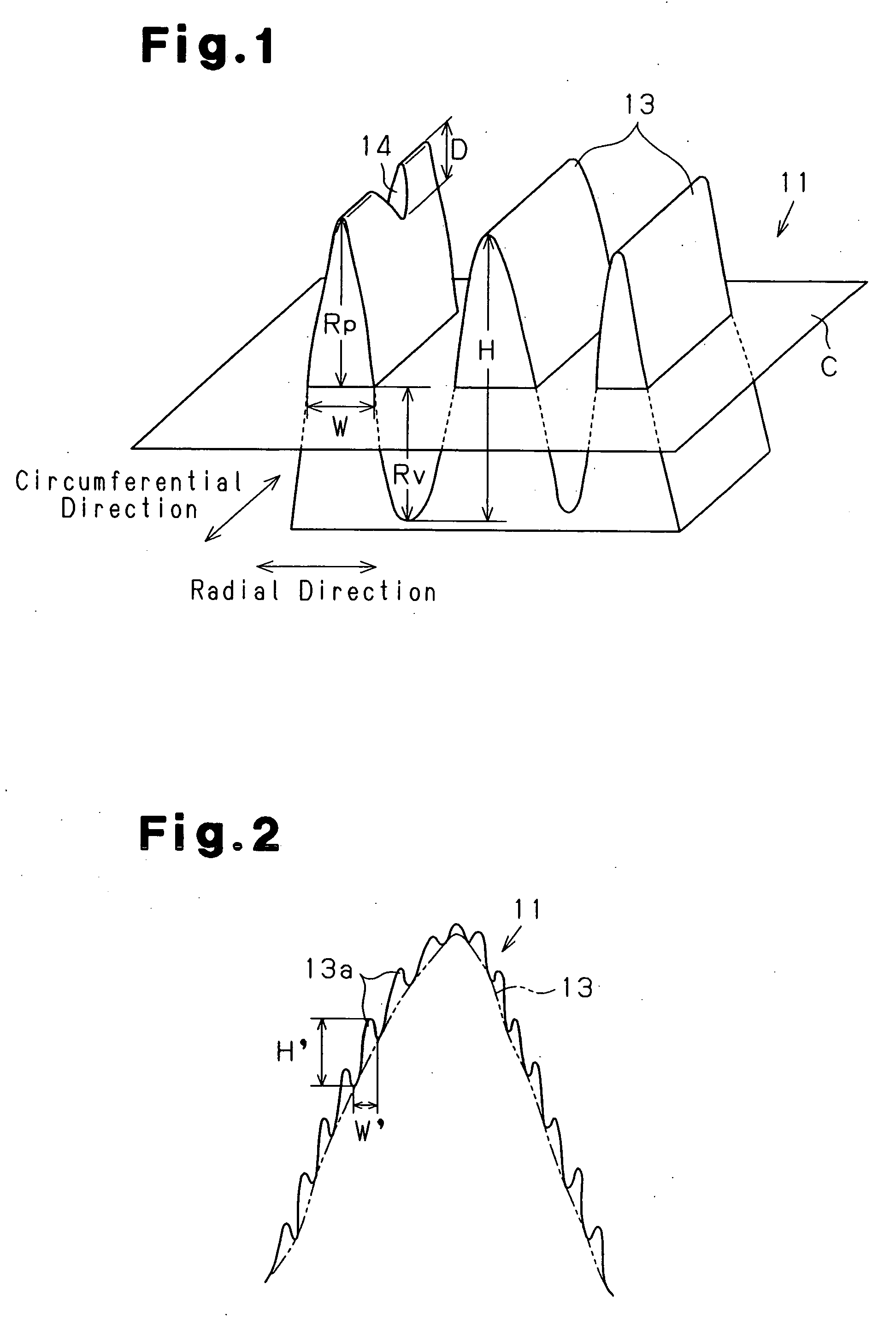
[0005] To achieve the above object, the present invention provides a glass substrate for a magnetic recording medium formed to have a disc shape and including ridge shaped textures extending along concentric circles on a main surface. The glass substrate is characterized in that the textures have a width W that is between 10 and 200 nm at a reference plane obtained by measuring a 10 μm square range with an atomic force microscope. The textures have a height H that is between 2 and 10 nm, and the textures have a ratio (Rp / RMs) of a maximum mountain height with respect to a root mean square roughness that is less than or equal to 15. The glass substrate achieves a lower levitation amount of a magnetic head and improves levitation stability.
[0006] It is preferred that the width W at a reference plane of the textures be between 10 and 20 nm. Further, in addition to the width W at the reference plane of the textures being between 10 and 20 nm, it is preferred that the height H of the textures be between 2 and 5 nm, and the ratio (Rp / Rms) of the maximum mountain height with respect to the root mean square roughness RMS of the textures be less than or equal to 3. In this case, the levitation amount of the magnetic head is further lowered, and levitation stability is improved.
[0007] It is preferred that when the textures are cut along a plane parallel to the main surface in the 10 μm square measurement range of the atomic force microscope, the percentage of the area of the cut plane with respect to the entire area of the measurement range is defined as a bearing ratio (BR), the height of the textures when the bearing ratio is 50% is defined as a reference height, and the height of the textures from the reference height in a plurality of bearing ratios is defined as a bearing height (BH), the difference between the bearing height (BH) when the bearing ratio (BR) is 0.01% and the bearing height (BH) when the bearing ratio (BR) is 0.4% be between 0.01 and 1.0 nm for the textures. In this case, projections that are abnormally projecting are decreased, the wear of the magnetic head is reduced, and levitation stability is improved.
[0012] It is preferred that the textures include low frequency components, obtained in the 10 μm square measurement range of the atomic force microscope, and high frequency components, obtained in a 1 μm square or 0.1 μm square measurement range of the atomic force microscope, superimposed on the low frequency components, and being finer than the low frequency components, and that the textures of the high frequency components have a width W′ that is between 0.1 and 20 nm, and the textures of the high frequency components have a height H′ that is between 0.1 and 1 nm. In this case, the magnetic anisotropy is enhanced, and the magnetic recording density at the textures is increased.
[0014] It is preferred that the textures in the 10 μm square measurement range of the atomic force microscope have a maximum valley depth Rv of 10 nm or less. In this case, local magnetic anisotropy is prevented from being lowered.
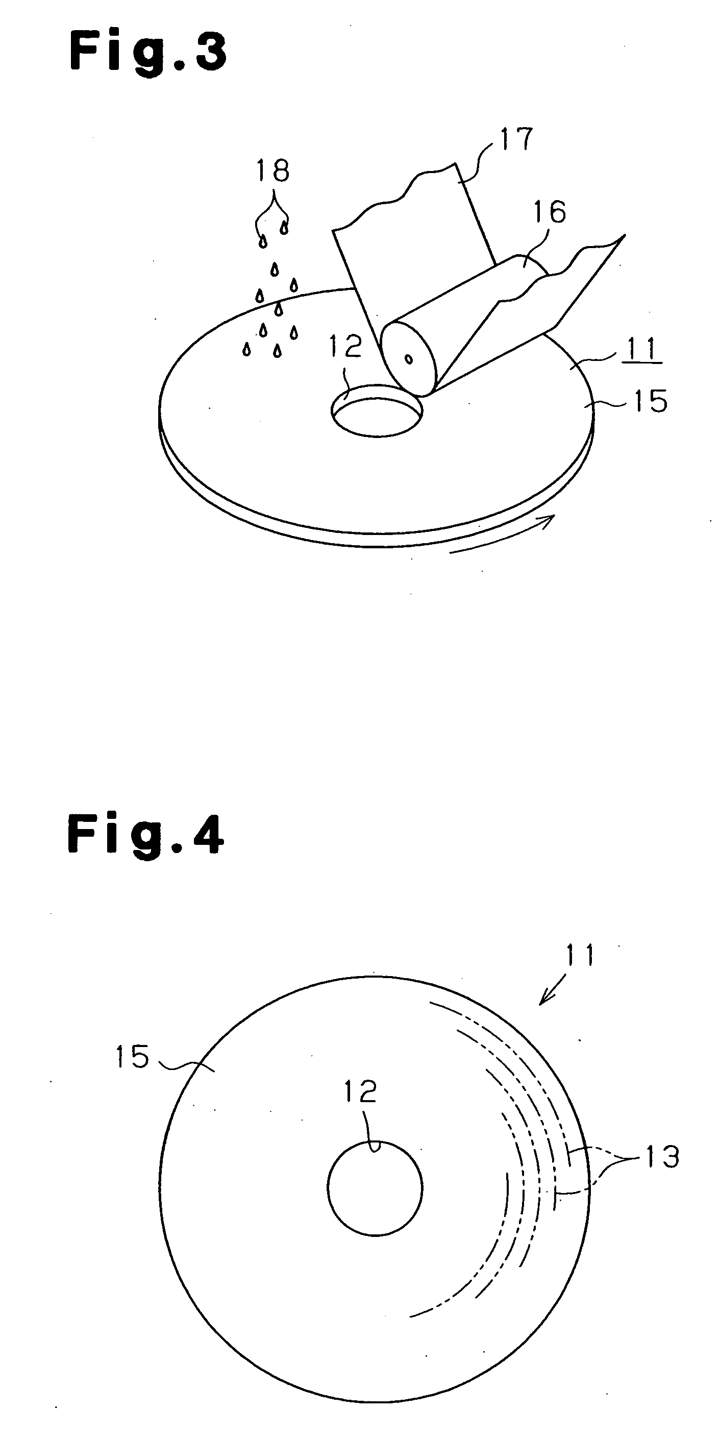
[0017] Another aspect of the present invention provides a method for manufacturing a glass substrate for a magnetic recording medium. The manufacturing method includes a disc machining process for machining a sheet of glass material into a disc shape, a polishing process for polishing a main surface of the disc-shaped glass substrate with a polishing member, a washing process for washing off residual polishing agent from the main surface of the glass substrate, and a texture formation process for forming textures on the main surface of the washed glass substrate. The method is characterized in that an arithmetic mean roughness Ra of the main surface of the washed glass substrate indicates a value of between 0.35 and 1.0 nm when a 10 μm square range is measured with the atomic force microscope. This method facilitates the manufacturing of a glass substrate including textures having a uniform shape.

Problems solved by technology

However, in the glass substrate having a texture with a small magnetic anisotropy in which the ratio of the coercive forces is between 0.90 and 1.10, the levitation stability of a magnetic head for reading information from the glass substrate cannot be realized, and low levitation characteristic is insufficient.

Method used


Image

  • Magnetic recording medium glass substrate and method of producing the same
  • Magnetic recording medium glass substrate and method of producing the same
  • Magnetic recording medium glass substrate and method of producing the same

Examples


example 1

[0096] A sheet of glass substrate 11 formed from aluminosilicate glass (63 mol % of SiO2, 16 mol % of Al2O3, 11 mol % of Na2O, 4 mol % of LiO2, 2 mol % of MgO, 4 mol % of CaO) is obtained through the float process. The glass substrate 11 was machined into a disc shape with a thickness of 1.0 mm, an outer diameter of 65 mm, and an inner diameter of 20 mm using a diamond cutter in the disc machining process 21.

[0097] Subsequently, in the inner and outer circumferential surface chamfering process 22, the inner and outer circumferential surface chamfering was performed on the glass substrate 11. In the main surface polishing process 23, lap polishing and smoothing were performed on the main surface 15 of the glass substrate 11. The smooth polishing was performed by polishing both surfaces of the glass substrate 11 using the polishing agent containing cerium oxide and a polishing pad having an Asker C hardness of 70.

[0098] In the post-polishing washing process 24, after removing the po...

examples 2 to 6

[0108] The manufacturing conditions of the glass substrate 11 were changed as shown in table 1, and a glass substrate having a width W and height H for the texture 13 and a ratio (Rp / RMS) of the maximum mountain height Rp and the root mean square roughness RMS for the texture 13 that are the same as in example 1 was obtained. The continuous seek test and the fixed point levitation test were conducted on the glass substrate in the same manner as in example 1. The results are shown in table 2.

TABLE 2Drive testContin-uousRp / SeekFixed Point LevitationW(nm)H(nm)RMS2000 hr24 hr48 hr72 hr96 hrEx. 11021.5NoNoNoNoNoEx. 21632NoNoNoNoNoEx. 32053NoNoNoNoNoEx. 42064NoNoNoNoYesEx. 55058NoNoNoYesEx. 62001015NoNoNoYesComp.25089YesYesEx. 1Comp.30088YesYesEx. 2Comp.733YesYesEx. 3Comp.61.52YesYesEx. 4Comp.1601.511YesYesEx. 5Comp.2001018YesYesEx. 6

[0109] As shown in table 2, in examples 1 to 3, the width W of the texture 13 was within the range of 10 to 20 nm, the height H of the texture 13 was withi...

examples 7 to 10

[0111] The manufacturing conditions of the glass substrate 11 were changed as shown in table 1, and a glass substrate having an average depth D of the depression 14 and a ratio H / D of the height H with respect to the average depth D of the texture 13 shown in table 3 was obtained in the same manner as in example 1. A continuous seek test and a fixed point levitation test were carried out on the obtained glass substrate 11 in the same manner as in example 1. The results are shown in table 3.

TABLE 3Drive TestContinuousFixed PointSeekLevitationD(nm)H / D2000 hr24 hr48 hr72 hrExample 70.115NoNoNoNoExample 8220NoNoNoNoExample 92.516NoNoYesExample 101.59NoNoYes

[0112] As shown in table 3, in examples 7 and 8, the average depth D of the depression 14 was less than or equal to 2 nm, the ratio H / D was greater than or equal to 10, and crash of the magnetic head did not occur in the continuous seek test and the fixed point levitation test conducted over 72 hours. In example 9, the average depth...


PUM

PropertyMeasurementUnit
heightaaaaaaaaaa
heightaaaaaaaaaa
widthaaaaaaaaaa

Abstract

A glass substrate for a magnetic recording medium is formed to have a disc shape and includes ridge shaped textures 13 extending along concentric circles on a main surface. When measuring a 10 μm square range with an atomic force microscope, the textures have a width W that is between 10 and 200 nm. The textures have a height H that is between 2 and 10 nm. Further, the textures have a ratio (Rp / RMs) of a maximum mountain height with respect to a root mean square roughness that is less than or equal to 15. The textures include high frequency components superimposed on the low frequency components. It is preferable that the textures of the high frequency components have a width W′ that is between 0.1 and 20 nm, and the textures of the high frequency components have a height H′ that is between 0.1 and 1 nm.

Description

TECHNICAL FIELD [0001] The present invention relates to a glass substrate for a magnetic recording medium such as a magnetic disc used as a hard disc of a computer or a magneto-optical disc, and a method for manufacturing the same. More particularly, the present invention relates to a glass substrate for a magnetic recording medium that further achieves a lower levitation amount of a magnetic head for reading magnetic data from a glass substrate surface and improves the levitation stability, and a method for manufacturing the same. BACKGROUND ART [0002] In the prior art, a known type of such glass substrate for a magnetic recording medium is described in, for example, Japanese Laid-Open Patent Publication No. 2002-32909. The glass substrate described in this publication includes concentric pits and lands formed on a main surface. The height of the pits and lands is of a size that does not have anisotropy in a circumferential direction when at least a magnetic film is formed on the s...

Claims


Application Information

Patent Timeline
Patent Type & Authority Applications(United States)
IPC IPC(8): G11B5/33C03C19/00C03C21/00G11B5/73G11B5/82G11B5/84
CPCC03C19/00C03C2204/08Y10T428/315G11B5/8404G11B5/7315G11B5/73921
Inventor ISHII, NORIMASAMITANI, KAZUISHISAITO, YASUHIROOKUHATA, KOJI
Owner HOYA CORP
Learn More