
Devices with multiple surface functionality

a technology of multiple surface functionality and devices, applied in the field of devices with multiple surface functionality, can solve the problems of blood thrombosis, increased inflammation, and decreased healing ra

Inactive Publication Date: 2006-08-31
PRINCETON UNIV
View PDF53 Cites 106 Cited by
  • Summary
  • Abstract
  • Description
  • Claims
  • Application Information

AI Technical Summary

Benefits of technology

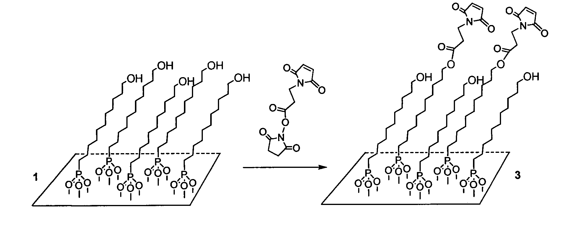
[0021] In one aspect, the present invention provides a medical device or an implantable device with one or more surface coatings covalently bonded to an oxide surface of one or more regions of the device to create different desirable surface properties on each region of the device surface. The coated medical device may be produced from an implantable substrate.

Problems solved by technology

For example, implant surfaces with long term exposure to blood may generate thrombus.
Inflammatory cells may also adhere to and proliferate on implant surfaces leading to increased inflammation and decreased healing rates.
When exposed to physiological conditions, the surface of a metal implant corrodes and leaches metal ions into the body.
Metal sensitivity may lead to implant rejection and require explantation.
Other metal ions, such as chromium, may have long term toxicity.
Infection presents a serious concern for implants.
Implantation or deployment of medical devices frequently causes injury at the site of deployment / implantation.
For example, balloon expandable stents injure the arterial wall when deployed resulting in inflammation that causes partial or complete restenosis of the artery.
Poor bonding with the interface between the metallic surface of the implant and the bone tissue leads to low mechanical strength of the bone-to-implant junction and the possibility of subsequent implant failure.
Currently, there is no effective way to obtain strong attachment of incipient bone with the implant material at the interface between the surfaces of the two materials in order to “stabilize” the implant.
The problem of interface synthesis is often approached from the prospective of high temperature methods, including using plasma or laser-induced coating techniques.
However, these methods engender problems of implant heating and surface coverage.
Therefore, control of surface stoichiometry can be problematic, and defects at the interface may translate into poor mechanical strength.
However, a practical limitation involving laser or plasma deposition is that it is hard to obtain comprehensive coverage on a titanium implant of complex 3-dimensional structure.
However, while solution-based procedures are inexpensive and give rise to materials resistant to dissolution by bodily fluids, adhesion of the hydroxyapatite to the implant metal is less strong than is observed when deposition is accomplished by plasma spraying techniques.
The deficiency of these solution approaches may lie in the nature of the native oxide surface of titanium materials.
But these phosphonic acid species fail to strongly adhere to the implant because they are not covalently bonded via heating.
In addition, Descouts does not disclose the preparation of different surface treatments on the same implant.

Method used


Image

  • Devices with multiple surface functionality
  • Devices with multiple surface functionality
  • Devices with multiple surface functionality

Examples


examples 1-3

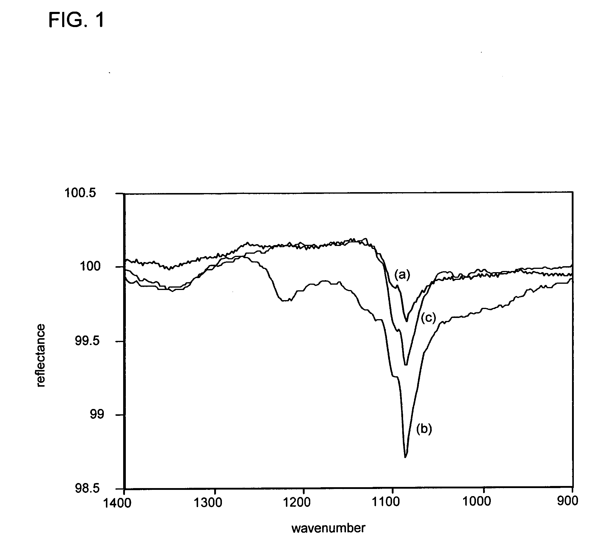
[0188] For the following Examples 1-3, ethanol (reagent grade) was obtained from Aldrich Chemical and used as received. 11-Hydroxyundecylphosphonic acid (a linear, 11-carbon-atom difunctional phosphonic acid having an ω-hydroxyl functional group to the phosphonic acid) was synthesized according to published procedures. Disks were cut from titanium Ti-6Al-4V rod (1′ in diameter, obtained from Goodfellow, Inc.) and prepared for use by sanding, followed by cleaning with methanol. The disks were dried for at least an hour before use, and stored in an oven at 200° C.

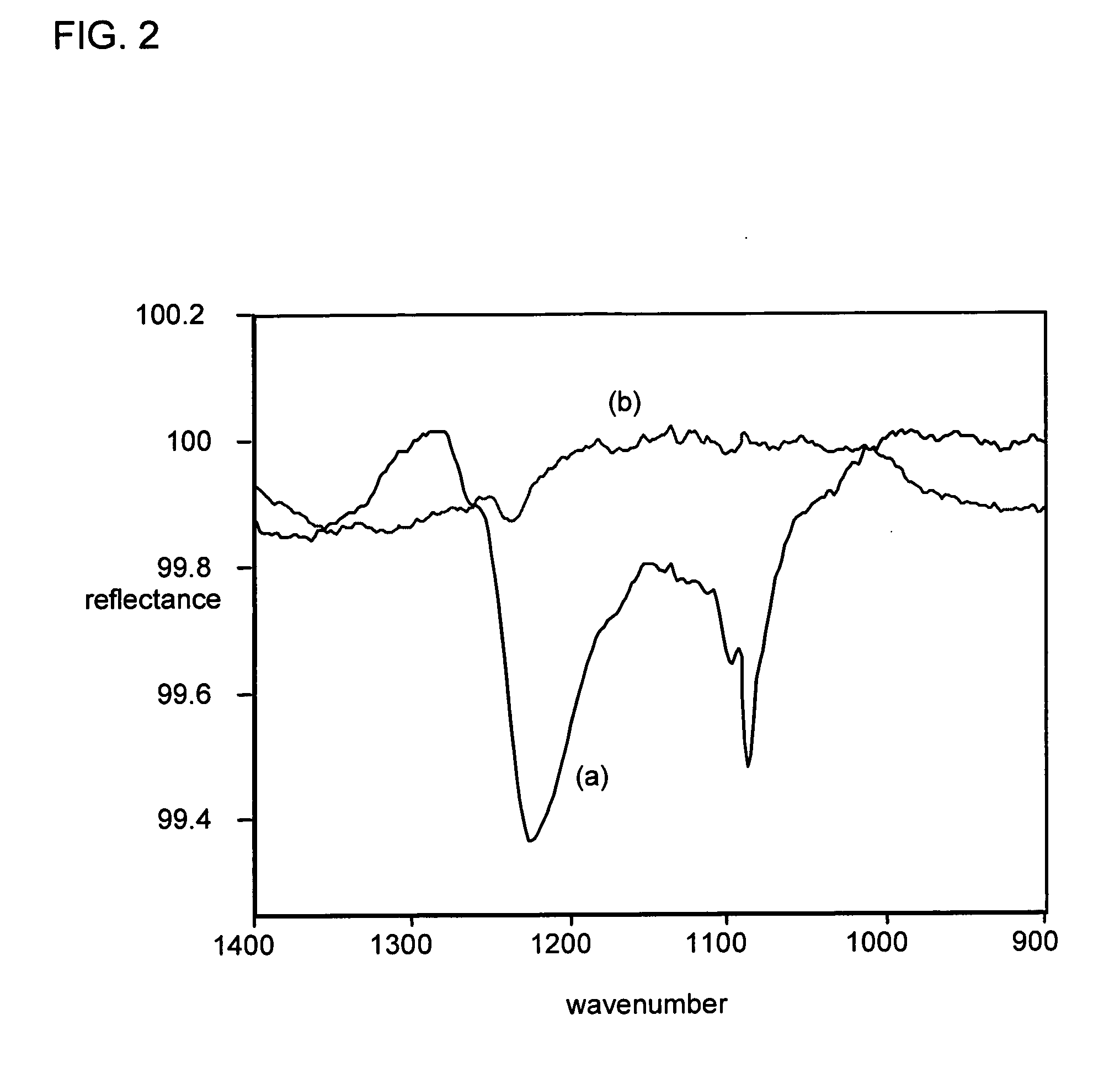
[0189] Samples were analyzed using either a Nicolet 730 FT-IR equipped with a Spectra Tech diffuse reflectance (DRIFT) attachment or a MIDAC Illuminator equipped with a Surface Optics specular reflectance head. When the Nicolet was used for analysis, infrared experiments were performed using a glancing angle attachment, a Variable Angle Specular Reflectance Model 500, obtained from Spectra Tech. The angle between the surface...

example 1

Application of a Coating Layer

[0190] A white cotton swatch of commercial textile measuring 2′ square was prepared as a carrier by rinsing in distilled water and drying in air. A 1.0 millimolar coating solution of 11-Hydroxyundecylphosphonic acid was prepared by dissolving 0.1 mM of the acid in 100 ml of ethanol. About 50 ml of the solution was placed in a shallow dish and the carrier was placed into the solution and saturated with it. The carrier was then removed from the solution and permitted to remain in air until it was visibly dry (overnight). Thus prepared, the carrier with containing a coating composition comprising 11-Hydroxyundecylphosphonic acid was placed over a titanium disk prepared as described above. A consumer cloth iron with a Teflon™-coated heating platen (Black & Decker) set for cotton cloth (no steam) was placed on top of the assembly for a period of 5 minutes. At the end of the heating period the iron was removed and the oxide substrate (titanium disk) was allo...

example 2

Deposition of a Coating Layer on a Metal Oxide Coated Plastic

[0193] A sheet of antireflective coated polyethylene oxide terephthalate (PET) which has a top layer of silicon dioxide will be obtained from Bekaert Specialty Films. Application of a cotton carrier prepared with a coating composition, as described above for Example 1, in accordance with the treatment procedure described above for Example 1 will be found to provide an 11-hydroxyundecylphosphonate coating to the antireflective coated plastic.


PUM

PropertyMeasurementUnit
thicknessaaaaaaaaaa
thicknessaaaaaaaaaa
thicknessaaaaaaaaaa

Abstract

Phosphorus-based coatings having a plurality of phosphate moieties, a plurality of phosphonate moieties, or both, covalently bonded to an oxide surface of an implantable substrate exhibiting one or more of the following characteristics: (a) the surface phosphorus-containing group density of the coated regions of the substrate is at least about 0.1 nmol / cm2; (b) the phosphorus-based coating has a thickness of less than about 10 nm; or (c) the surface phosphorus-containing group density of the coated regions of the substrate is equal to or greater than the surface hydroxyl group density of the oxide surface of the substrate. Implantable devices embodying the coated substrates are also disclosed.

Description

CROSS-REFERENCE TO RELATED APPLICATIONS [0001] The present application claims priority to U.S. Provisional Application No. 60 / 643,647 filed Jan. 13, 2005; U.S. Provisional Application No. 60 / 643,648 filed Jan. 13, 2005; U.S. Application No. 60 / 684,159 filed May 25, 2005; U.S. Application No. 60 / 699,498 filed Jul. 15, 2005; and, U.S. Application No. 60 / 707,525 filed Aug. 12, 2005, the entire contents of all of which are hereby incorporated by reference. [0002] This application is also a continuation-in-part of U.S. application Ser. No. 10 / 876,294, filed Jun. 23, 2004, which claims priority to U.S. Provisional Application No. 60 / 480,670, filed Jun. 23, 2003, which in turn is a continuation-in-part of U.S. application Ser. No. 10 / 405,557, filed Apr. 1, 2003, which claims priority to U.S. Provisional Application Nos. 60 / 369,236 and 60 / 369,237, both filed Apr. 1, 2002, which in turn is a continuation-in-part of U.S. application Ser. No. 10 / 179,743, filed Jun. 24, 2002, which claims prior...

Claims


Application Information

Patent Timeline
Patent Type & Authority Applications(United States)
IPC IPC(8): B28B11/00A61F2/958
CPCA61L27/32A61L29/106A61L31/086B05D1/185B82Y30/00B82Y40/00Y10T428/265C03C17/23C23C14/06C23C22/02C23C22/48Y10T428/131Y10T428/12611C03C17/001A61P31/00Y10T428/12556
Inventor SCHWARTZ, JEFFREYGAWALT, ELLEN S.ALVATRONI, MICHAEL J.
Owner PRINCETON UNIV
Learn More