Coincidence counting method of gamma ray and nuclear medicine diagnostic apparatus

a technology of coincidence counting and gamma rays, applied in the field of coincidence counting methods of rays, can solve the problems of inability to use low-energy rays and inability to extend the time window, so as to minimize the influence of other rays

Inactive Publication Date: 2006-08-31
HITACHI LTD
View PDF4 Cites 3 Cited by
  • Summary
  • Abstract
  • Description
  • Claims
  • Application Information

AI Technical Summary

Benefits of technology

[0012] According to the coincidence counting method of a γ ray and the nuclear medicine diagnostic apparatus of the present invention (the invention of the first aspect), the detection time of a γ ray is corrected according to the energy of the detected γ ray. Thus, even the time window has the same width, coincidence counting can be precisely performed over a wider range of energy. Further, for example, the time window can have a fixed narrow width, thereby minimizing the influence of other γ rays detected spontaneously.
[0013] Further, according to the coincidence counting method of a γ ray and the nuclear medicine diagnostic apparatus of the present invention (the invention of the second aspect), the width of the time window can be varied (corrected) according to the energy of the detected γ ray. Thus, the coincidence counting can be precisely performed on γ rays over a wide range of energy. Moreover, it is possible to minimize the influence of other γ rays detected spontaneously as compared with the case where the time window remains wide.

Problems solved by technology

However, in some cases, γ rays interact with water and elements consisting of a detector and are scattered in a living body and the detector, and the γ rays lose some energy thereof (in vivo scattering, Compton scattering).
Further, it was found that when coincidence counting is performed over a wide range from high energy γ rays not being scattered (γ rays in the PP area) to low energy γ rays having been scattered (γ rays in the CS area), the low energy γ rays cannot be used due to the time difference unless the time window widened.
Moreover, a wider time window is not preferable because other γ rays with different sources are more likely to be detected spontaneously.

Method used


Image

  • Coincidence counting method of gamma ray and nuclear medicine diagnostic apparatus
  • Coincidence counting method of gamma ray and nuclear medicine diagnostic apparatus
  • Coincidence counting method of gamma ray and nuclear medicine diagnostic apparatus

Examples


embodiment 1

[0029] First, regarding Embodiment 1 using scattered ray with a fixed time window, a principle, a concrete example, and the operations of the concrete example will be discussed in this order.

[Principle]

[0030] The principle of Embodiment 1 will be discussed below.

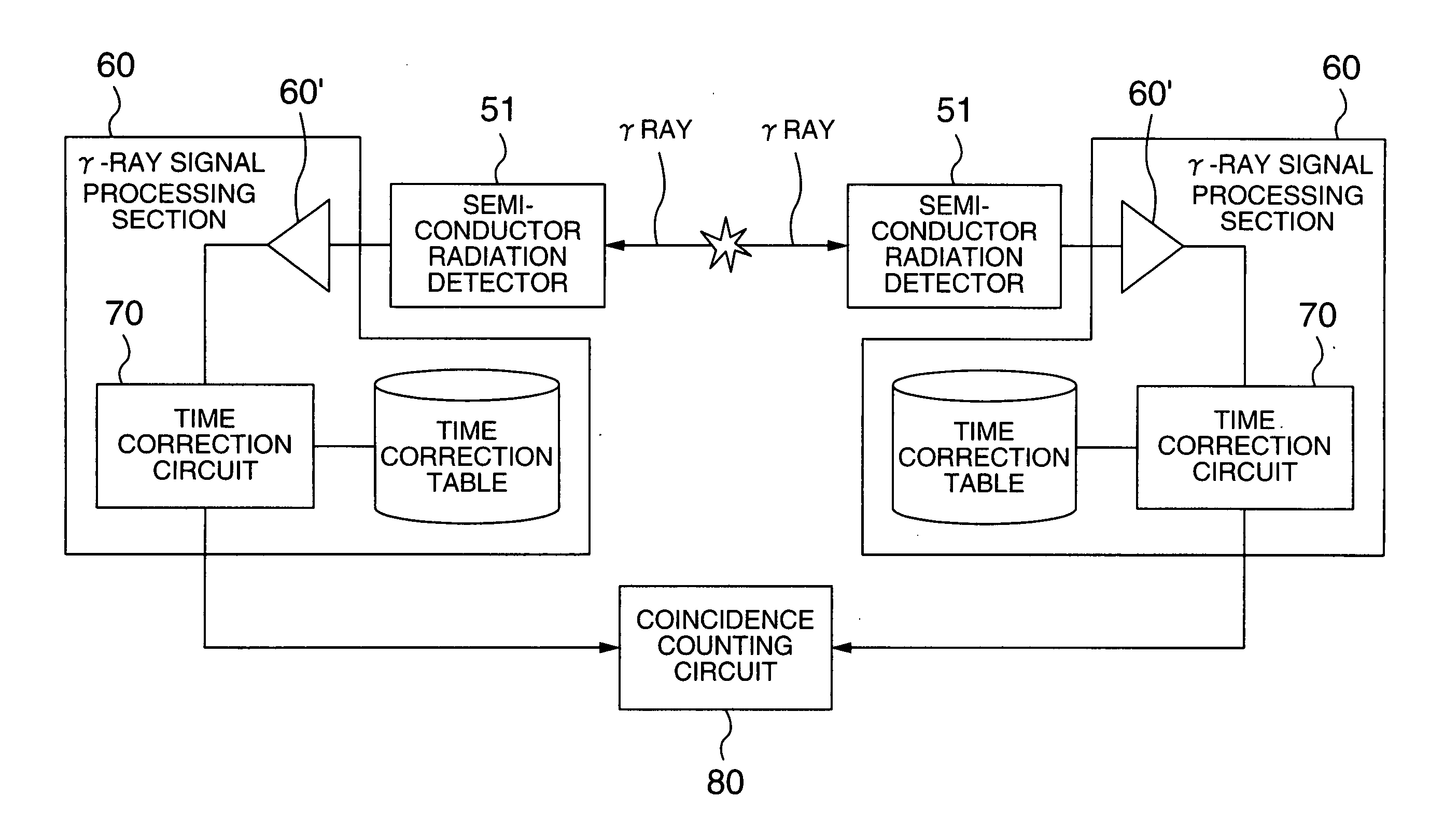
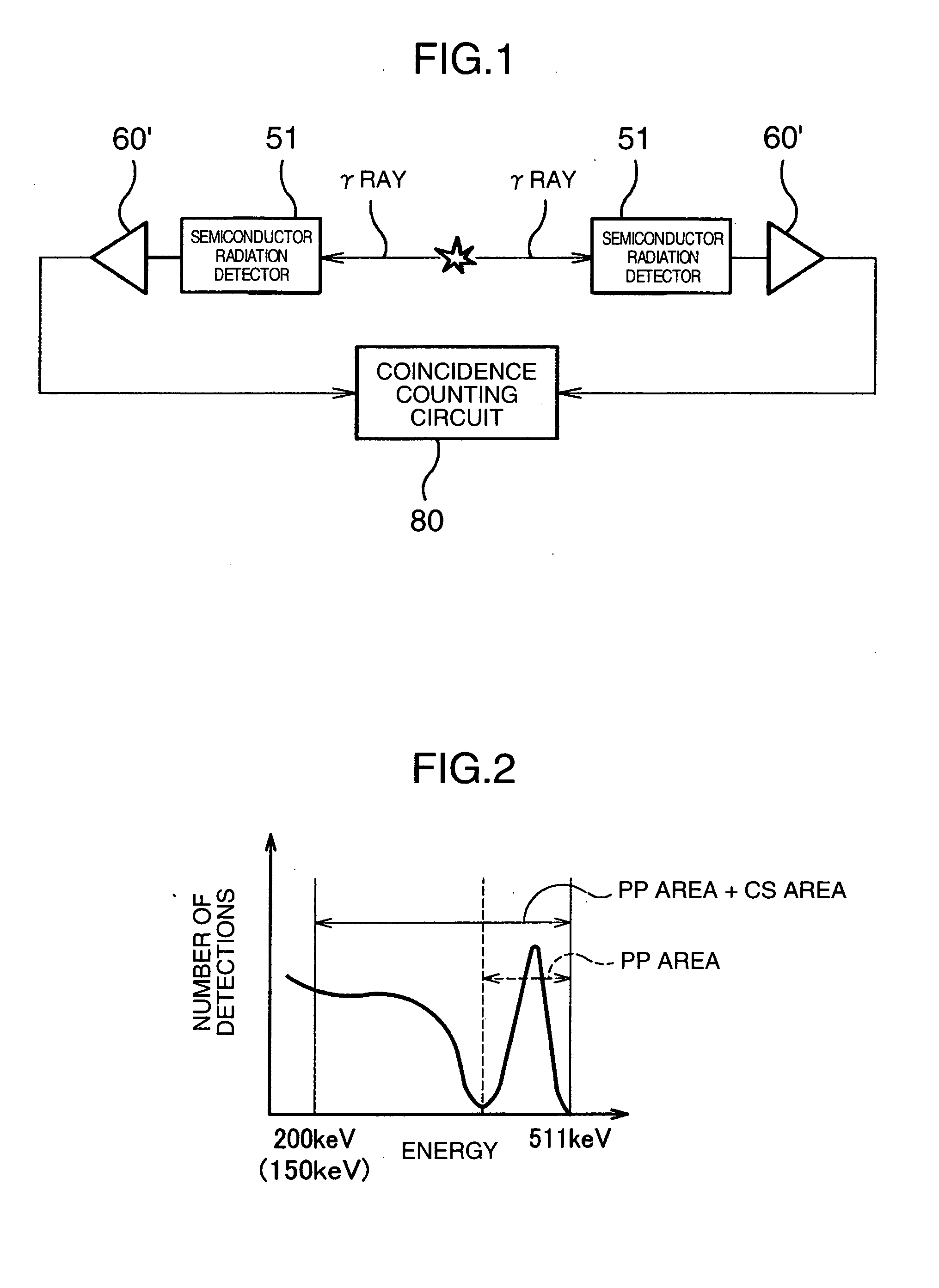
[0031] First, the present inventors clarified the relationship between energy (peak value) of a γ ray detected by a semiconductor radiation detector 51 and a difference in detection time (detection time difference) by using an experimental apparatus simplified in FIG. 1. The experimental apparatus of FIG. 1 comprises the semiconductor radiation detector 51 which acts as a detector for detecting γ rays and is made of cadmium telluride (CdTe), a circuit (γ-ray signal processing section 60′) which has the function of determining the energy of a detected γ ray and determining a detection time, and a coincidence counting circuit 80 which has the function of measuring a detection time difference relative to energy based on the ...

embodiment 2

[0065] Regarding Embodiment 2 using scattered ray with a variable time window, the following will discuss a principle, a concrete example, and the operations of the concrete example in this order. An explanation about the same parts as Embodiment 1 is omitted.

[Principle]

[0066] The principle of Embodiment 2 will be discussed below.

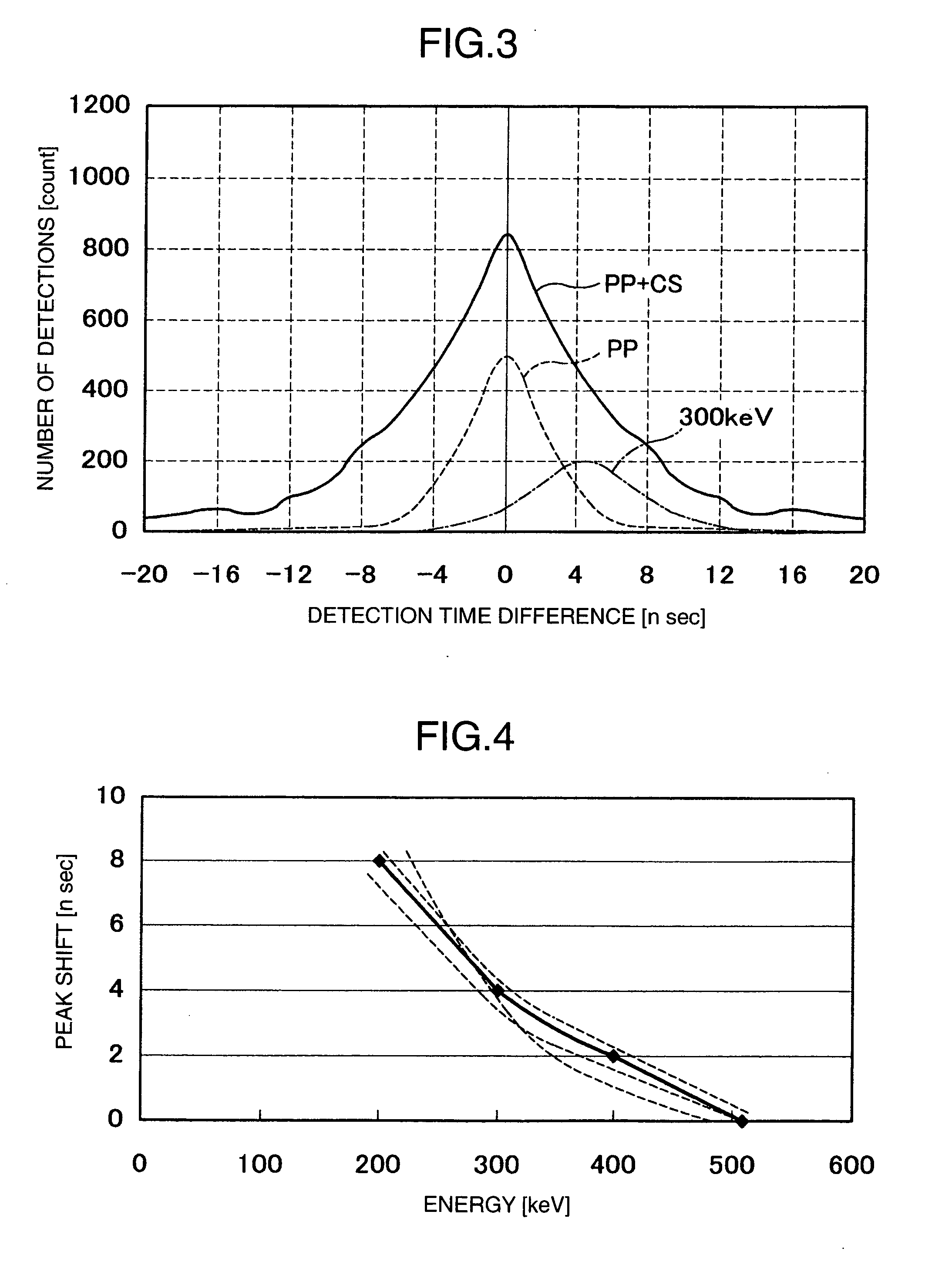
[0067] According to the experiments using the experimental apparatus (FIG. 1) described in Embodiment 1, the present inventors found that a difference in detection time (detection time difference) occurs according to the energy of a γ ray (FIG. 3). Based on this knowledge, a detection time is corrected in Embodiment 1 (FIGS. 4 and 5). In Embodiment 2, a time window is corrected instead of a detection time.

[0068] In FIG. 10 showing an example of a time window correction table, a horizontal axis represents a difference in energy between successively detected 7 rays (keV) and a vertical axis represents a correction value (nsec) of the time window. As is un...

concrete example

[0070] Referring to FIG. 11 and others, a concrete example of Embodiment 2 will be discussed below.

[0071] A PET apparatus 1′ of Embodiment 2 is similar in appearance to that of Embodiment 1 (FIG. 7). As shown in FIG. 11, a γ-ray detection signal detected by a semiconductor radiation detector 51 is processed in a γ-ray detection signal processing section 60′. Unlike the γ-ray detection signal processing section 60 of Embodiment 1, the γ-ray detection signal processing section 60′ has a typical configuration not having a time correction circuit 70 (or a time correction table). This is because Embodiment 2 makes a time window variable instead of correcting the detection time of a γ ray.

[0072] As shown in FIG. 11, a coincidence counting circuit 80′ of Embodiment 2 comprises a time window correction table 81. The coincidence counting circuit 80′ has the function of making the time window variable and performing coincidence counting using the first inputted signal (signals (N, τ, E) fro...


PUM


Abstract

A γ-ray signal processing section 60′ determines a detection time of a γ ray based on a α-ray detection signal outputted from a semiconductor radiation detector for detecting the γ ray, and determines the energy of the γ ray. Then, a time correction circuit 70 obtains, based on the energy of the γ ray, a detection value of the detection time that corresponds to the energy of the γ ray from a time correction table indicating the relationship between the energy of the γ ray and the correction value of the detection time of the γ ray, and corrects the detection time according to the obtained correction value of the detection time. Coincidence counting is performed on the γ ray in a coincidence counting circuit 80 based on the corrected detection time.

Description

BACKGROUND OF THE INVENTION [0001] The present invention relates to a coincidence counting method of γ rays (gamma rays) in a nuclear medicine diagnostic apparatus, for example positron emission tomography (PET). [0002] Diagnostic methods and diagnostic apparatuses are known in which a radioactive agent such as fluorodeoxyglucose (FDG) is injected to a patient and annihilation γ rays, which are emitted simultaneously in pairs in opposite directions from the body, are detected to create a functional image (PET image). In such diagnostic methods and diagnostic apparatuses, γ rays emitted in opposite directions from the body are simultaneously detected by two of a plurality of detectors provided in the diagnostic apparatus, so that the incident direction (emitting direction) of the γ ray is identified and a PET image used for a medical diagnosis is created. Considering that a detection time is delayed in the detectors, processing is delayed in a detection circuit, and three or more γ r...

Claims


Application Information

Patent Timeline
Patent Type & Authority Applications(United States)
IPC IPC(8): G01T1/164G01T1/161G01T1/172
CPCG01T1/172
Inventor YANAGITA, NORIHITOUENO, YUUICHIROUAMEMIYA, KENSUKEKITAGUCHI, HIROSHITSUCHIYA, KATSUTOSHIKOJIMA, SHINICHIYOKOI, KAZUMAISHITSU, TAKAFUMI
Owner HITACHI LTD
Why Eureka
Try Eureka